Yet Another 3D Printer Enclosure and Dry Box
by 3D Challenged in Workshop > 3D Printing
2100 Views, 5 Favorites, 0 Comments
Yet Another 3D Printer Enclosure and Dry Box

This instructable is intended to be used as a guide should you wish to build an enclosure for your 3D printer. As such there are no dimensions provided as your printer may require an enclosure that is larger or smaller than the one I built.
Shortly after purchasing my Creality Ender 3 Max I discovered that it did not like the cool air that inhabited my office in the winter. Unless the room was heated to a temperature where it was uncomfortable for me be in the likelihood of the PLA filament remaining stuck to the heated bed was slim. So when summer rolled around I decided to build a heated enclosure for the printer.
I am also pretty cheap…some might say frugal. Being of this mindset I used as much material as I could from the stuff sitting in the garage and basement for years or that I could scrounge…I’m not proud! I was also able to print many of the parts I needed, which in itself was a very good learning experience.
The following is the story of my 3D printer enclosure along with a bonus dry box build. To be honest, this is not a quick build and will cost you some cash if you have to buy all the materials. How much…I don’t know.
Supplies
Tools:
It is very handy, and in some cases necessary, to have some of the following tools or a friend who has the tools you do not have and that may be too expensive to buy. Fortunately, I have a couple of such friends.
- Table saw: The saw blade should be a 50-Tooth (T) or higher to make a clean cut in acrylic (plexiglass). Blades with fewer teeth could result in chipping the acrylic.
- Hand saw: If a table saw is not available a hand saw can be used to cut wood and acrylic. Do some research before using a hand saw to cut acrylic.
- Circular saw: This can be used to cut the wooden parts. I would not use it to cut acrylic. To get straight cuts on the MDF it would be good to use a circular saw cutting guide. You can buy these or just use a straight board and a couple of clamps for the two ends.
- Electric drill: For drilling holes into the enclosure.
- Flat hole drill bits: For smaller holes up to 1 inch.
- Drill bit hole saw: For larger holes up to 6 inches.
- Standard drill bits: These should be rated for wood, metal and plastic in order to get clean holes in the acrylic.
- Woodworking clamps: These will help in the construction of the enclosure. The bigger the better.
- Bungee cords: If you can’t get a hold of large clamps, like me, these can be used to hold things together when needed. They are also a lot cheaper than clamps.
- Caulking gun: For applying adhesives purchased in tubes.
- Sander: A random orbit or palm sander to finish the outside of the enclosure. Manual sanding would also work but would take forever.
- Sandpaper: For whatever sander you may be using. 120 grit works fine.
- Nuts, bolts, washers, screws: I gathered these from a selection of jars and boxes in the basement. You can pick up what you need when you know what sizes are required. I printed washers if I did not have what was needed.
Materials:
All the materials are available at your local hardware store.
- MDF (Medium Density Fibreboard): I used one quarter inch MDF for the four walls of the enclosure because I had it available. The quantity you will need will depend upon the size of the enclosure being built.
- Plywood: I used one quarter inch plywood for the top and bottom of the enclosure because I had it available. The plywood was doubled to make it half inch thick. The quantity you will need will depend upon the size of the enclosure being built. If I did not have the plywood available I would have used the MDF and doubled it.
- Acrylic sheet: I was gifted some quarter inch acrylic sheet for the door.
- Bubble wrap foil insulation: This is used to insulate the inside walls, floor and ceiling of the enclosure.
- Inside corner moulding: As the MDF was only a quarter inch thick the wood moulding is used to reinforce the vertical corners. I had this sitting in my basement for a few decades. I knew it would come in handy someday.
- Plastic corner guard: I also had some of this in the basement and it is used to protect the outside corners of gyproc walls. Each side is a half inch wide and finishes off the outside corners of the enclosure nicely.
- Foil tape: This tape is used to seal the joints on metal ducting and is about 2 inches wide. This was used on the edges of the acrylic door as well as a base for gluing hinges, latches and the handle on the door. As a result there are no holes drilled into the acrylic.
- Adhesive: The enclosure uses no screws or nails to hold it together. I used LePage PL FAST GRAB PREMIUM Construction adhesive. Did you know it was 8X stronger? Anyway, once this stuff sets the only way to take it apart is destructive.
- Silicone: This is used to glue the bubble wrap foil insulation to the inside walls of the enclosure and parts to the acrylic door and on the outside wall. I used GE Window and Door Advanced Silicone.
- Stain: I had two colours leftover from other projects that I used, one for the top and bottom of the enclosure and the other for the sides.
- Polyurethane: A couple coats of this gives the stain an excellent finish.
- Paint: I had some black rust paint that made the clear plastic corner guard look much better and hid the joint under it. When I ran out of the spray paint I opened a can and used a brush.
Additional Components:
The following items were installed to provide greater control over the heating of the enclosure.
Many of these items were obtained through stores on Aliexpress. I will provide details but no links as often these disappear. It is easy enough to search for these items and pick the store you want to deal with. Since then I have found another source for items…TEMU. If you can find what you want on TEMU shipping is faster and so far service has been good.
- Ceramic heater: I bought a 900/1500 watt 120 Vac ceramic heater at a thrift store. It is installed in the enclosure to help bring it up to temperature at the start of printing. I operate this at 900 watts because the current rating of the temperature controller does not support 1500 watts. A single stage heater in the range of 500 watts would be adequate.
- Brushless exhaust fan: This 120Vac fan is 120x120x25 mm and is rated for an air flow of 87 cfm. It is used to keep the enclosure temperature from getting too high by exhausting hot air from the top of the enclosure thus forcing cooler outside air to enter the enclosure.
- Brushless cross flow fan: This 24VDC fan is 260x60x60 mm. This fan was sitting in a desk for decades so I do not have a flow rating as it is too old to find any specifications. It is used to minimize temperature stratification in the enclosure by drawing hot air from the ceiling of the enclosure and pushing the air down the back wall.
- Activated carbon filter: This comes in various sized sheets for air purifiers and is used with the cooling fan as it vents into the room.
- Temperature controller: I used a XH-W3001 controller rated for 120Vac and so does not require a DC power supply. It can be used for either heating or cooling control. Two are used to control the ceramic heater for heating and the exhaust fan for cooling.
- AC motor speed controller: I had a couple of these from long ago. The speed controller is used with the exhaust fan should I want to slow it down for any reason.
- Dual display voltmeter/ammeter: I bought a couple of these some time ago just because. They are used to monitor the 3D printer’s voltage and current output. The current shunt in the meter is only rated for 10 amps but the power supply can put out just over 14.5 amps at 24VDC. So I wired two of them in parallel.
- Blade car fuse: The two voltmeter/ammeter displays wired in parallel could pose a problem if one fails and all the current goes through the other display. It will be fried. A 10 amp fuse is wired into the circuit of each display to protect it. I got these fuses from a car that was being demolished.
- AC Fuse holder and glass fuse: The relay in the temperature controller is rated for 10 amps. The ceramic heater operating at 900 watts will draw 7.5 amps. If it were set to 1500 watts it would draw 12.5 amps, which is well above the rating of the relay. Should this happen the temperature controller would be damaged. The fuse holder with an 8 amp fuse protects the temperature controller from being accidently overloaded.
- Temperature/humidity display: There are all kinds of these available with and without remote probes. They are useful for placing in various locations in the enclosure should you want to do so. A display is required for the dry box.
- USB hub, mini lights, and power adapter: These 3 items will give a light source for inside the enclosure. Place the power adapter outside the enclosure and tie wrap the USB hub to the printer frame. Just make sure the power adapter can supply the current required by the number of mini lights installed.
- Switches: Toggle and/or pushbutton switches are required for the heater and two fans.
Remember, none of these items are required to construct the enclosure. The printer build plate and nozzle will heat the enclosure and the door can be opened to cool it.
Stuff to Make:
As you want to build a 3D printer enclosure I will presume you already have a printer as I did. You now have to make some stuff. The items you will be making depend upon what you plan to include as part of your enclosure. That will be up to you.
I will be telling you about the items I made with my printer for my enclosure. There is so much available out there that I did not have to design one part. Some of the parts were straight forward print files and some used OpenSCAD, which is a free software application for creating solid 3D computer-aided design objects. It is a script-only based modeller that uses its own description language and requires some effort if you wish to design an item from scratch. It is very easy to use if you are using scripts developed by those that know what they are doing. This does not include me. The script allows you to change the parameters of the part to meet the requirements of what you want to use the part for.
You will need to download OpenSCAD from here: https://openscad.org/
The following picture shows some of the parts required for the enclosure.
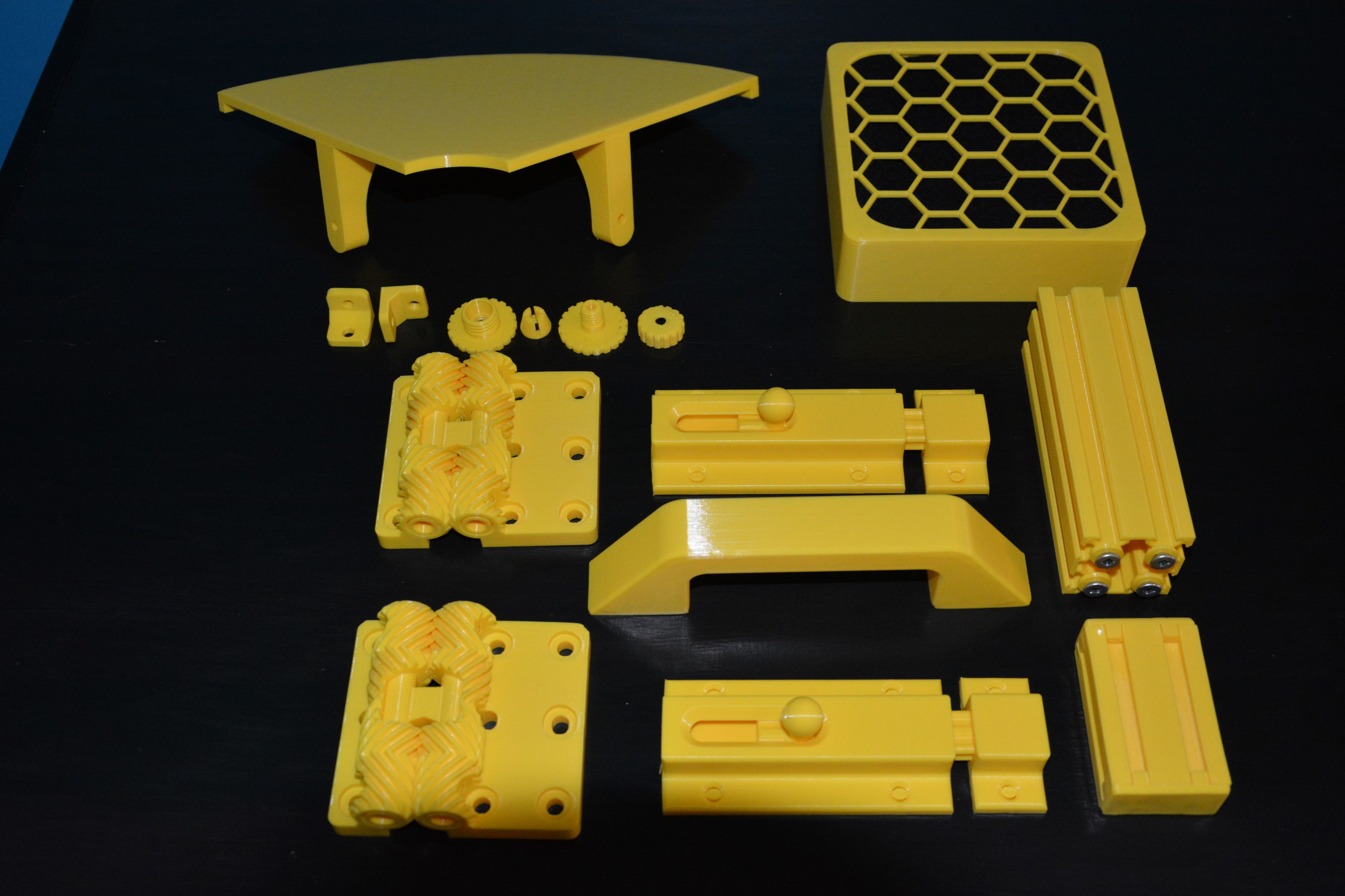
- Box Corner Protector: A way to finish the corners. Here it is: https://www.thingiverse.com/thing:603832/files
- Door hinges: I was looking for a unique door hinge and found a print in place geared hinge. This hinge can hold a lot of weight but considering they are holding a light acrylic door I used the default slicer settings. Here it is: https://www.printables.com/model/120766-print-in-place-geared-hinge
- Door handle: If you are looking for customizable door handles check out: https://cults3d.com/en/3d-model/home/fully-customizable-general-purpose-handles
- Sliding door bolt: The sliding portion of the bolt can be printed in place as one piece. Here it is: https://www.thingiverse.com/thing:1596180
- Corner shelf: This was used for the ceramic heater and includes a pass through at the back for the cord. It is an OpenSCAD script and the shelf can be sized to whatever you need. Here it is: https://www.thingiverse.com/thing:2824359
- Fan filter: This is for mounting the active carbon filter to the inlet of the exhaust fan. Printing as is required filing the plastic fan frame to make it fit. Here it is: https://www.thingiverse.com/thing:2752346
- PTFE Tube Connector: This is used to route filament from outside the enclosure into the enclosure. It is also used for the dry box. There are many ways to do this but I used a design that required no screws. Here it is: https://www.thingiverse.com/thing:2954028
- Electronics box: A box is needed for the wiring and components associated with the two temperature controllers. A box was needed for each of the voltmeter/ammeter displays. A box was needed for the on/off switch for the cross flow fan. An OpenSCAD script allows you to design boxes of any size. The box can include mounting tabs if needed and up to 3 holes on any one side for wiring to enter. Here it is: https://www.printables.com/model/72839-stable-and-waterproof-electronic-box-enclosure
- Hole plug: There are three holes in the bottom front of the enclosure. I put them there to be used as air inlets if required but I did not want them to be left open so plugs were needed. An OpenSCAD script allows you to design plugs of any size. Here it is: https://www.thingiverse.com/thing:4634255
- Washers/spacers: There were instances when I needed washers and spacers that I did not have. An OpenSCAD script allows you to design washers and spacers of any size. Here it is: https://www.thingiverse.com/thing:953338
- Power supply bracket: These were used to mount the printer power supply on the outside of the enclosure. This is a simple bracket used with spacers to position the power supply as needed. Here it is: https://www.thingiverse.com/thing:1054389
- 2040 extrusion and endcaps: To move the filament holder outside the enclosure I needed a 2040 extrusion and two endcaps to finish it off. The end caps were difficult to install. I used a heat gun to soften the extrusion and then push the end caps on. There are a number of files available for these items so it is best to find one you would like to try.
- 4040 extrusion: To move the LCD display board outside the enclosure I needed a 4040 extrusion but no end caps. Again, there are a number of files available for this item so it is best to find one you would like to try.
- Shelf bracket: Mounting the filament holder on the outside of the enclosure required a shelf bracket to help support it. I found some unique brackets here: https://thangs.com/designer/DaveMakesStuff/3d-model/Ten%20Top%20Opt%20Shelf%20Brackets-316331
Getting Started
You will need to decide how much of the 3D printer will be inside the enclosure. I moved the filament holder, power supply and display panel outside the enclosure. Moving the filament holder reduced the size of the enclosure significantly. Moving the power supply and display unit removed them from a potentially hot environment to a place that is much cooler and better for the electronics.
You will need to decide how large the enclosure needs to be: length, width and height. Make sure to move the build plate to both ends of the Y-axis and check carefully for any protruding cables or other items that may add extra distance. Then make the enclosure larger so you have room inside for stuff you might want to add later. How much is up to you.
You will need to decide how large the door opening needs to be. My opening requires rotating the printer to get in into the enclosure but this was done intentionally. This was to make the frame for the door as large as possible and still get the printer in and out.
Now you can gather all your tools and materials. I do not have workshop and the build was done in the garage on a 4x8 foot sheet of plywood on four sawhorses. So I gathered materials as was needed.
The Basic Box
I did not intend to write about the construction so I did not take any photos. But what you want to end up with is something similar to what is shown below. I will describe to you how to achieve this. It is quite simple but time consuming. Here we go.

- I have a friend with a table saw. After determining the size of the plywood and MDF pieces required I went to his place and we cut all pieces.
- Before starting the assembly all the wood pieces were sanded on the side that would be visible. This smoothened and cleaned them nicely.
- The top and bottom of the enclosure were made from quarter inch plywood repurposed from an old window valence. There are two layers glued with the LePage adhesive to give a finished thickness of one half inch. The valence pieces were too small to make each layer a single piece. Each layer is made of two pieces cut so they can be crisscrossed when glued together. This results in one solid piece of wood.
- The remainder of the enclosure was made from one quarter inch MDF that had been lying about in the garage. No screws or nails were used in assembling the pieces. Once the LePage adhesive sets it is impossible to take the glued pieces apart without causing severe damage.
- The top and bottom plywood pieces sit inside the MDF pieces. This provides half an inch of vertical plywood surface around the edges to glue the MDF to. This will give a strong bond along these surfaces. The two side MDF pieces were cut to the same length as the plywood. This requires the back MDF piece to be cut one half inch wider than the plywood to allow the back piece to overlap the two side pieces.
- The one quarter inch overlap of the back piece over a side piece is not sufficient to provide a strong bond when glued together. This is where the inside corner moulding is used. The moulding is place vertically in the corners and the side and back pieces are glued to the one half inch wide surface the moulding provides.
- The front of the enclosure is made from MDF pieces sized to give the required size for door opening. This frame is actually two layers of MDF to give a final frame thickness of one half inch. The first layer and the two vertical corner moulding pieces are inset so the first layer is flush with the edge of the top, bottom and side pieces. There are 4 first layer pieces, two vertical and two horizontal. The horizontal pieces are cut the full width so they can be glued to the corner moulding pieces. The 4 pieces are shorter and narrower to meet the door opening dimensions. The 4 second layer pieces are cut to have the joints crisscross and to extend to the outer edges of the top, bottom and side pieces. This makes the frame stronger.
- The assembly took a number of days. As the joints were glued they needed to be secured with bungee cords, clamps and pieces of wood. The adhesive was then allowed to set until the next day. Then the procedure was repeated on more joints. With the tools I had that was the only way I could do it.
- Three 1 inch holes were drilled along the bottom of the door frame to be used as air inlets if required. I printed plugs that would fit in the holes to close them off when they were not needed.
- A 4 ½ inch hole was drilled into the upper right hand corner of one of the sides for the exhaust fan. I was able to borrow a hole saw as good ones this size are expensive.
- Some of the adhesive squeezed out of the joints and required some additional sanding to clean it up.
- Once I had the outside of the enclosure looking decent it was time to apply the stain. The plywood top and bottom were stained black. The MDF surfaces were all stained a reddish colour. I applied 3 coats of stain.
- After the staining was complete I applied 3 coats of clear gloss polyurethane. By applying subsequent coats after 2 hours sanding between coats was not required.
- The staining and application of polyurethane took a few days to complete.
- The bubble wrap foil insulation was installed inside the enclosure using the GE silicone adhesive. Pieces were cut to size for the sides, back, top and bottom. Smaller strips were used for the front frame. The strips were sized to extend one half inch into the door opening. A second layer of one half inch strips was glued to the top of the extensions. This was done to provide somewhat of a seal when the door is closed and latched.
- The 3d printed corner pieces were glued on using the GE silicone adhesive.
- After painting the plastic corner guard strips with black paint they were cut to length and glued to all the edges using the GE silicone adhesive.
- The enclosure was finished and now the door could be installed.
The two black strips of MDF on the floor of the enclosure were to set the printer on. These were positioned after the printer was placed in the enclosure and were attached to the floor using silicone. This was necessary as the vibrations when the printer was operating would move it around inside the enclosure.
The Door
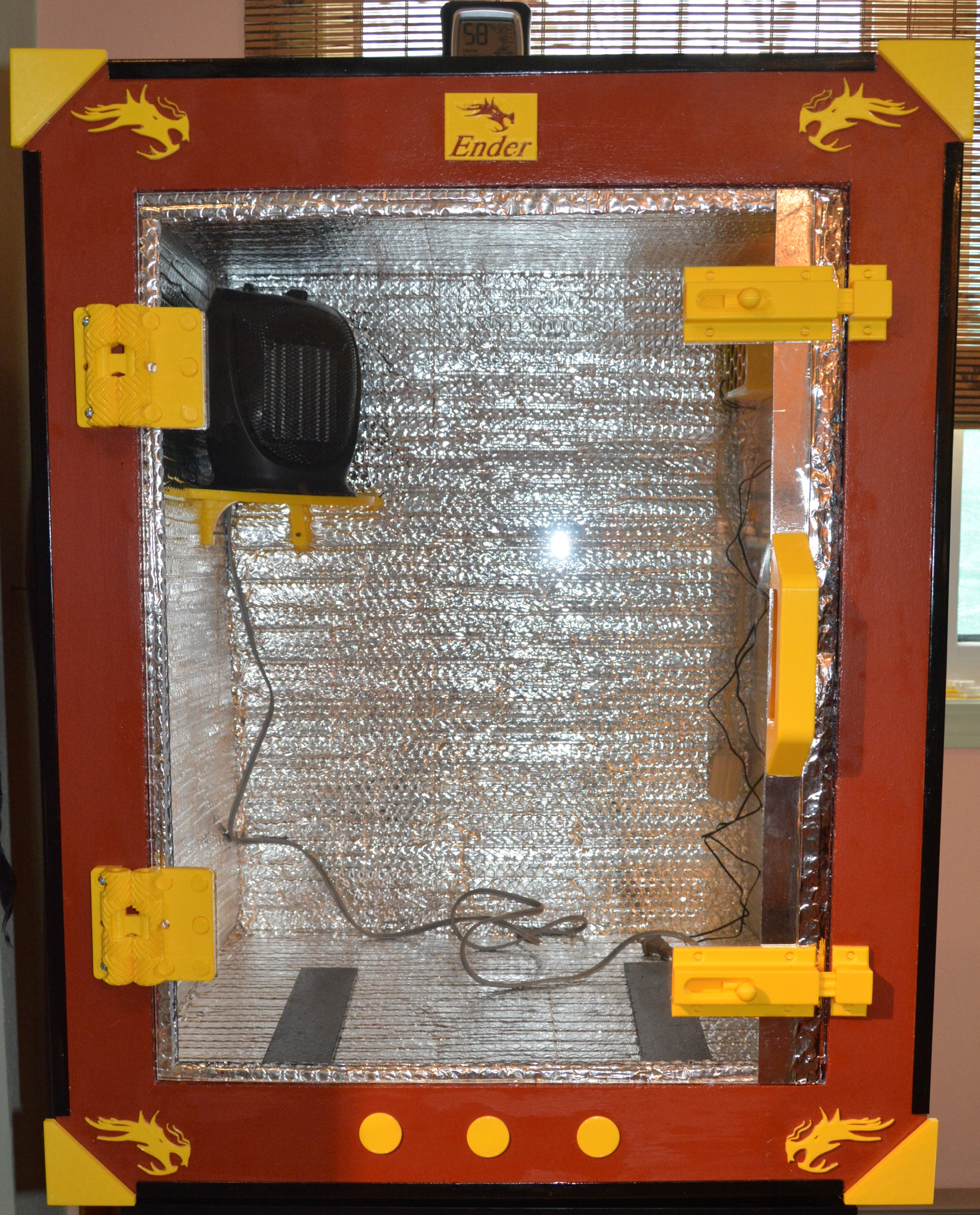
Acrylic is not cheap and I was very happy to receive a piece from a friend. It was a quarter inch thick, longer than the opening but half an inch too narrow. I had planned to drill holes in the acrylic to mount the hinges, latches and handle. I even bought drill bits that were rated for plastic. I did come up with a method of attachment that required no drilling.
- Again, I have a friend with a table saw. Only one cut was required to shorten the acrylic to the required length. When cutting acrylic a saw blade with a minimum of 50 teeth (50T) should be used to get a clean cut. The cut should be made slowly to prevent overheating the acrylic. There is a ton of information out there regarding different methods of cutting acrylic. Some I would not use.
- Wherever I used the foil tape I first cut the pieces in half lengthwise. This gave strips one half inch wide.
- To make up for the shortness in the width I cut a strip of bubble wrap foil insulation one half inch wide. I then secured the strip to the edge of the door with foil tape.
- I ran the foil tape around the perimeter of the door because it looked good. The tape was folded around the edge of the door.
- I determined where I wanted the hinges to be located. First I tried to silicone the hinges to the door but the bond between the hinge and the acrylic was poor. I then put pieces of foil tape on the door where the hinges were to be located. The tape bonds extremely well to the acrylic. I then used silicone to attach the hinge to the foil tape. This made an excellent bond. I printed plugs for the holes in the hinges where the bolts were to go.
- I also did this for the sliding door bolts and handle. The part of the door bolt on the frame was also secured with silicone adhesive.
- I positioned the door in the opening and marked the position of the hinge bolt holes on the frame. Nuts and bolts were used to mount the door to the frame as a silicone bond would not be strong enough.
This all worked very well and I was pleased with how the door looked and operated.
The Filament Holder and Feed Through
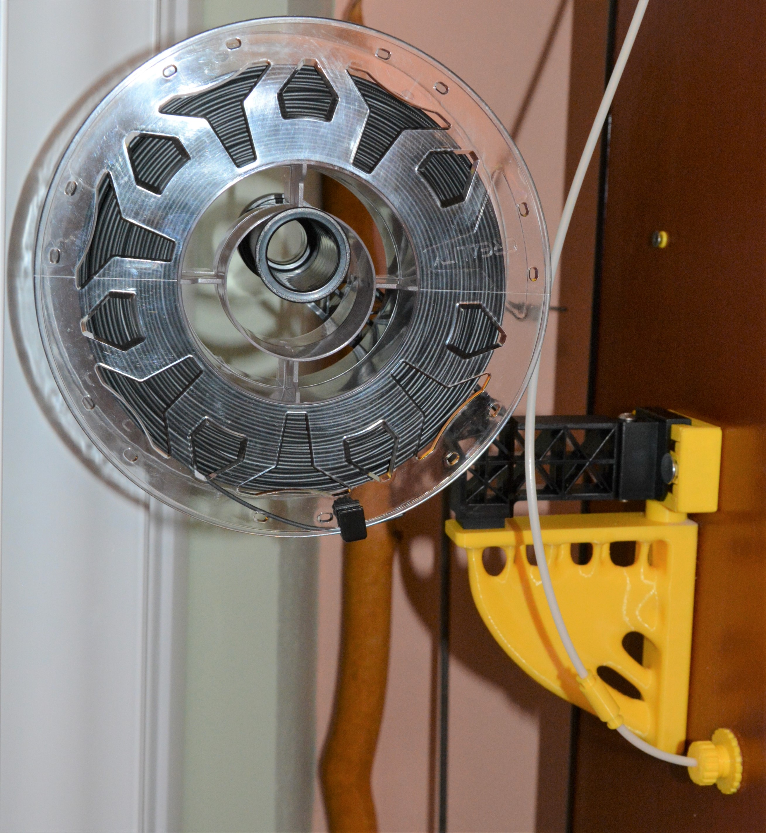
The filament holder on the printer was mounted on the left side 2040 extrusion. It had a pad that would rest on the desk/table to support the weight of the filament roll.
- To mount the filament holder on the side of the enclosure I printed a length of 2040 extrusion. It ended up being shorter than planned as it released from the build plate before finishing. However, it was long enough. The extrusion was bolted on the wall through holes drilled into the reset portions of the extrusion.
- As the filament holder would now be suspended it would not rest on any surface to provide support. I printed a unique shelf bracket, found the correct location for it and bolted it to the side of the enclosure.
- I printed two end caps for the extrusion but they did not fit. I used a heat gun to soften the each end of the extrusion and then was able to push the end caps on. This worked but is not as good as if they actually fit. It was adequate.
- I printed a PTFE tube connector to route the filament into the enclosure. The file I used was for a plastic dry box so it was too short to make through the one quarter inch MDF and insulation. A friend modified the file to make the part longer so it would fit. There are many designs out there but I liked this one as it did not require screws or bolts.
LCD Display Board and Power Supply
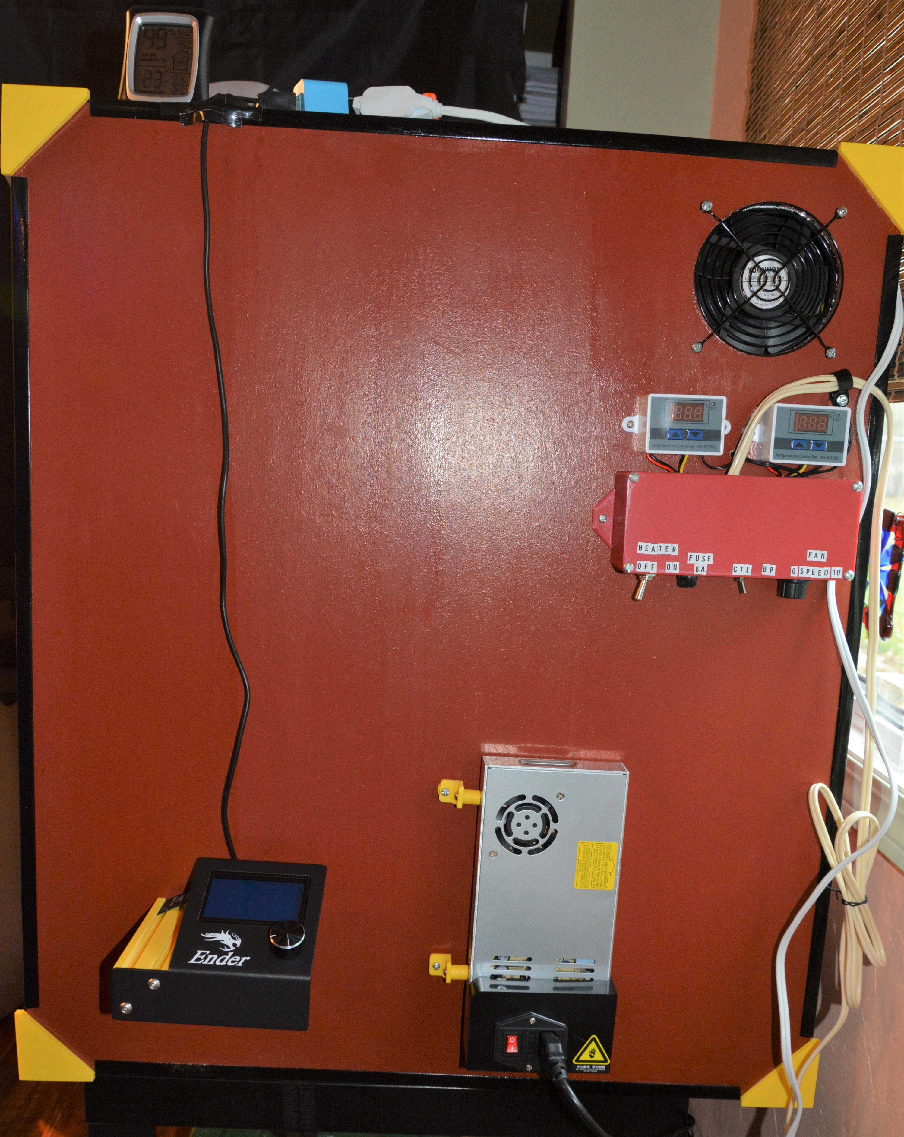
The LCD display board and power supply were moved to outside of the enclosure. This gives better access to the display board and puts both items in a cooler environment.
- I printed a length of 4040 extrusion to mount the lcd display board on. The length will depend upon how far from the enclosure the display needs to be to clear the wall. Four screws from the inside of the enclosure secure the extrusion and the original screws were used to mount the display. By carefully working the screws back and forth I was able to get them into the extrusion holes prior to the final install. You need to consider the length of cable available coming from the control board to the display. I had purchased what I thought was a longer cable but it turned out to be the same length as the original. However, by routing the cable through the opposite end of the control board case it was able to reach the display.
- To mount the power supply I printed a couple of brackets and some spacers. Two short spacers are used to keep the power supply away from the enclosure wall. I reused the original mounting bolts and so two longer spacers were needed to ensure the bolts did not go too far into the power supply and potentially cause problems. The length of these spacers was based on the distance measured where the power supply was originally mounted. The power supply was positioned to ensure the wiring could reach it from inside the enclosure. Unlike the display, there was plenty of wire length.
- The holes for the display and power supply cables were kept as small as possible.
Temperature Controls
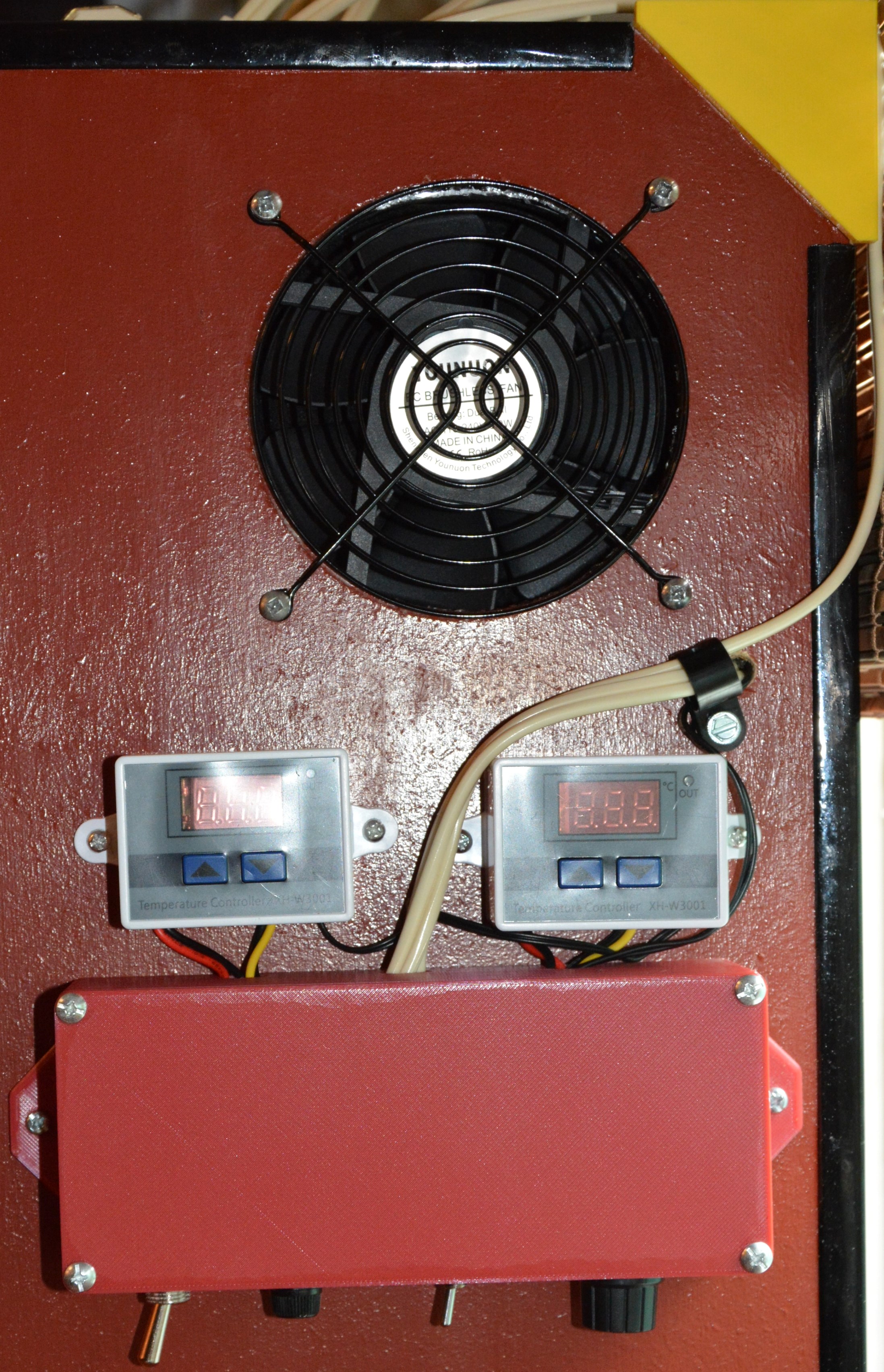
There were two temperature controllers installed and an on/off switch for the cross flow fan.
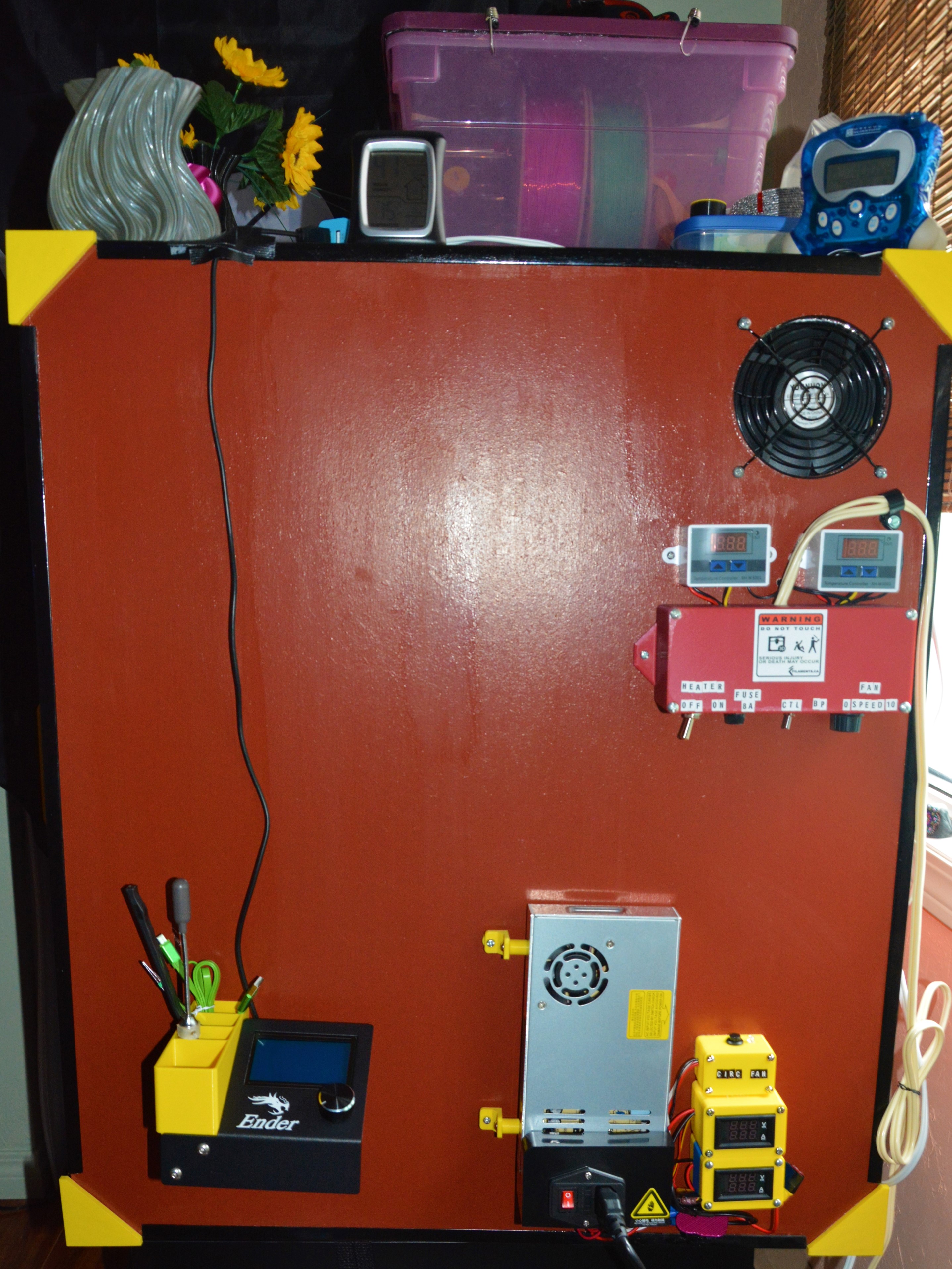
- An electronic box was printed for the wiring and some other items associated with the two temperature controllers. This is the red box in the photo and it included mounting tabs to bolt it to the wall. The box size and the three holes located on the top of the box were configured in the OpenSCAD script. The holes in the bottom of the box were drilled to size after the box was printed. The temperature controllers are bolted above this box.
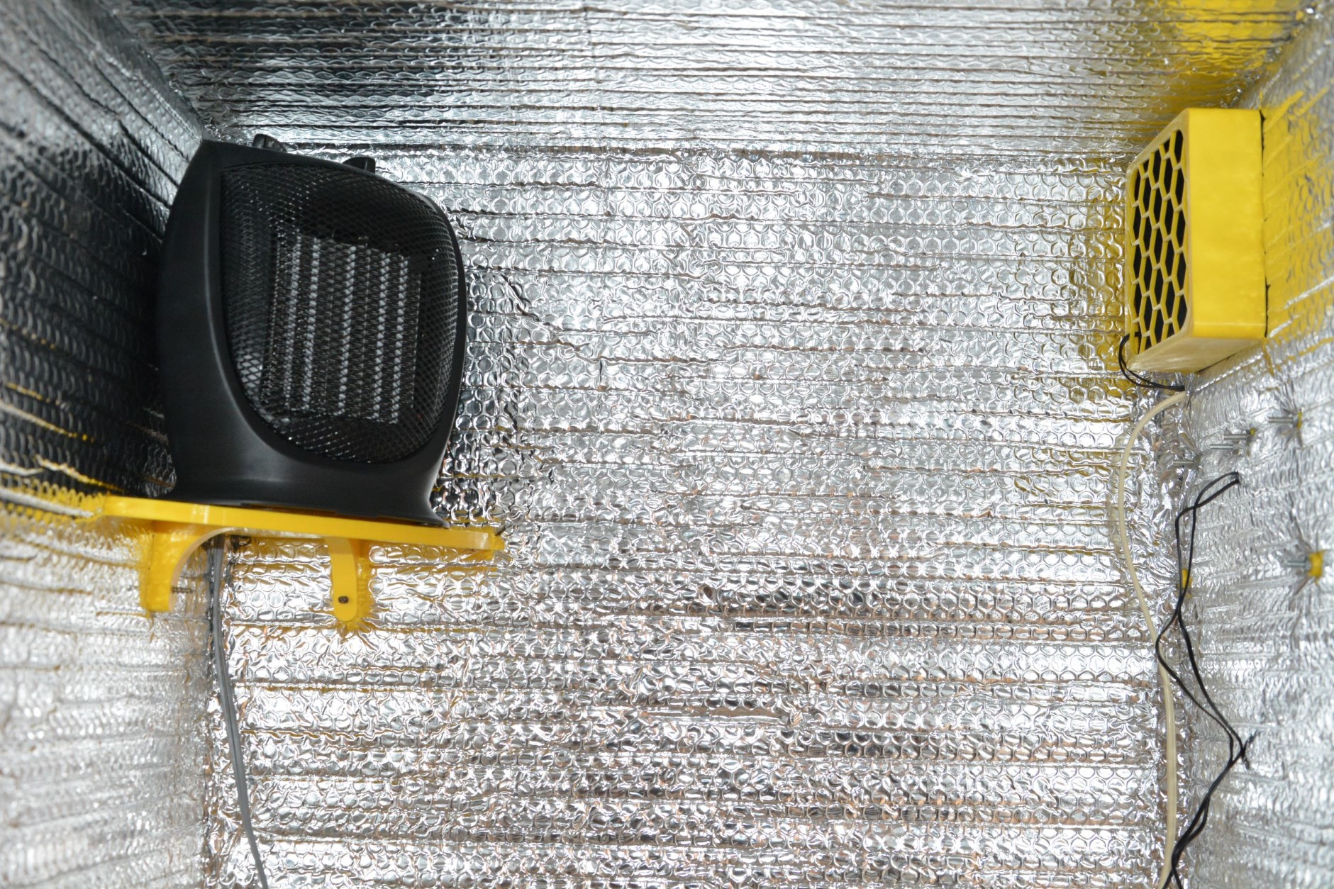
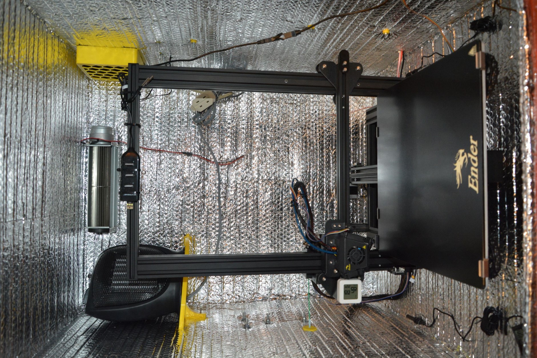
- The controller on the left is configured for heating and controls the space heater located in the upper left corner inside the enclosure. Its sensor is tie wrapped to the top rail of the printer.
- The controller on the right is configured for cooling and controls the exhaust fan just above it. Its sensor is also tie wrapped to the top rail of the printer.
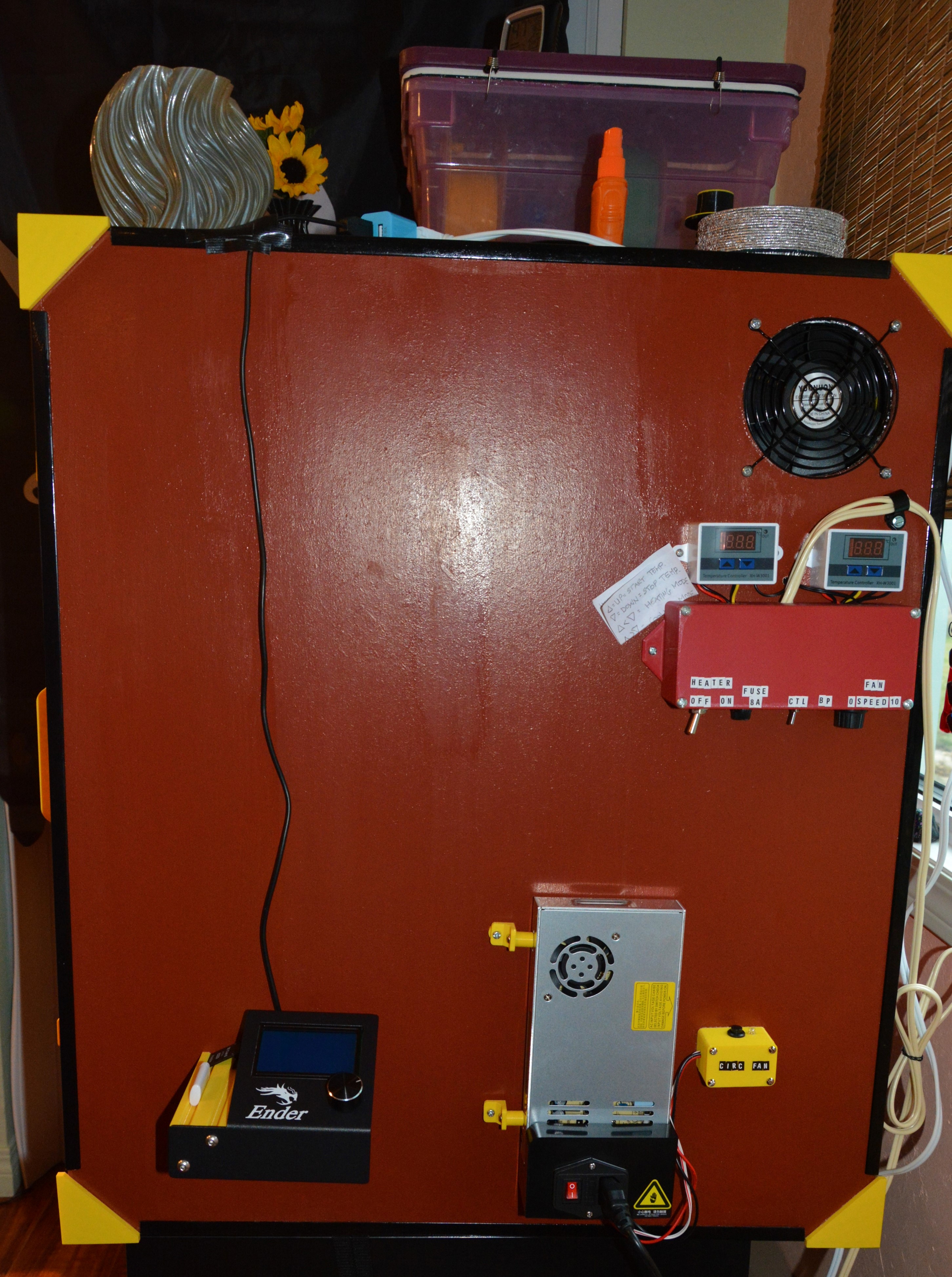
- The items mounted on the box, from left to right, are:
o On/off toggle switch for the heater. The current rating for this switch must match the heater rating.
o 8 amp fuse to ensure the 10 amp rating of the controller is not exceeded.
o Toggle switch to select if the exhaust fan is controlled by the controller or manually.
o Exhaust fan speed controller. I had it so I put it in. The speed controller works regardless of the position of the toggle switch.
- All the above items operate on 120 Vac without any ground. For the incoming power and heater power cables I used two wire extension cords and just cut off the end that needed to be hard wired. The exhaust fan is only 3 watts and the wires that came with it were long enough to reach the controller. I made sure of that.
- The cross flow fan was mounted on the rear wall as close to ceiling as possible. The fan draws the hot air from the ceiling and pushes it down along the back wall. It pretty much eliminated the temperature stratification that was happening before it went in. I tried this fan because I had it. The fan operates on 24 VDC and draws about 350 mA so I connected it to the printer power supply as it is 24 Vdc. The smallest yellow box contains the latching on/off pushbutton switch and a colour changing LED light to show when it is operating. It was attached to the wall with silicone. I have these LEDs that change colours when energized so I thought I would use one. All that was required was a properly sized resistor that would drop the voltage from 24 volts to that required by the LED.
- The calculation of resistor value for any LED is as follows:
o R = (Vps – Vled) / Iled
o R - resistor value in ohms
o Vps - power supply voltage
o Vled - LED operating voltage
o Iled - LED operating current
o Vled and Iled are available from the LED specifications.
o The resistor is wired in series with the LED and the two are wired in parallel with the load.
The Completed Enclosure
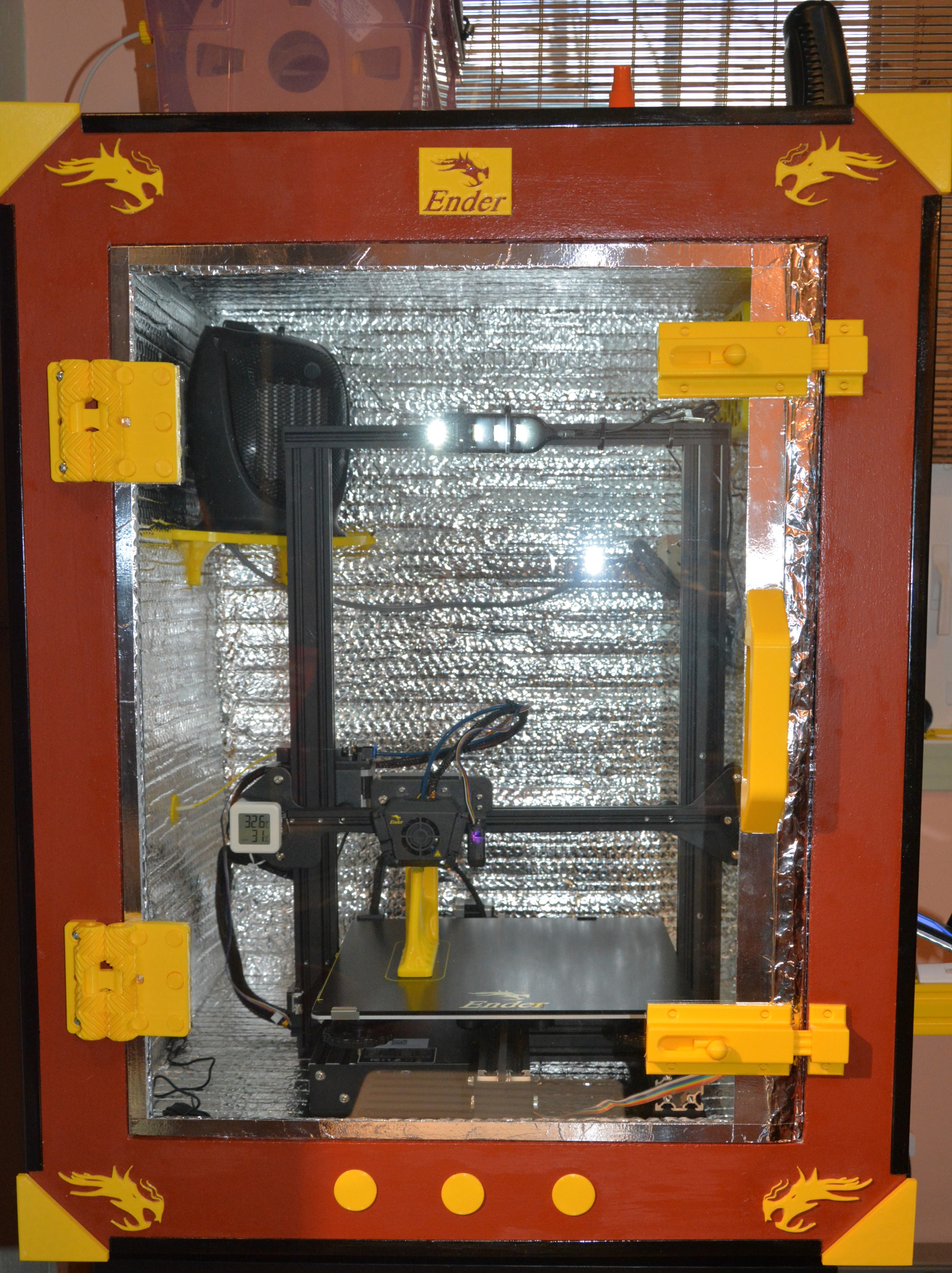
Here are some photos of the completed enclosure.
Other Displays
I used to wonder how much current was drawn from the printer power supply. I had a couple dual display voltmeter/ammeter modules kicking around and was wondering if I could use them. The power supply is rated for 350 watts at 24 VDC. So its maximum current rating is about 14.6 amps. The displays were rated for more than 24VDC but could only handle 10 amps. The current limit is a result of the current shunt being in the display itself. With external current shunts higher ratings can be achieved. But that’s what you get with cheaper displays.
What to do? As I had two displays I wired them in parallel so each one should show half the current draw and as a result increase the total current that could be read to 20 amps. But if something went wrong with one display the second display would get all the current, which could be greater than 10 amps. I installed a 10 amp car fuse in each circuit to protect the displays if that should happen. I made fuse holders using two insulated female spade crimp connectors that were taped together. I saw this in video once. Make sure they are insulated or use heat shrink to make them so. If not the connectors could short and the fuse would be useless.
In use, the two current readings are not the same as would be expected. The readings would be identical only if the two circuits had identical resistance characteristics. This is not likely to be the case. There is also the accuracy and calibration of the displays to take into consideration. In any case, adding the two readings gave the total current draw and is just what I was looking for.
The two larger yellow boxes contain the displays. They were attached to the wall with silicone. The OpenSCAD script designs these boxes with a solid top. I was going to use a rotary tool to cut the opening for the display. Instead I took the OpenSCAD file into a piece of software called FreeCAD where I cut out the opening and created a STL file. I then printed the boxes with the opening in the top. This worked very well.
I also placed some temperature and humidity displays inside the enclosure. These are cheap and can give you an idea of what is happening inside there. They can be read through the acrylic door.
Decoration & Lighting
I found a file for the Creality Ender 3 dragon here: https://www.thingiverse.com/thing:3296398
It made a nice addition to the front of the enclosure.
I had some mini lights that plug into a USB port. I tie wrapped a 4 port USB bub to the top rail of the printer and routed a USB extension cable from a power adapter located on the top the enclosure to the USB hub. The power adapter is plugged into an extension cord. This gives plenty of light.
Safety
You read a lot about 3D printer fires and to never leave them alone. I installed a smoke the detector inside the enclosure as a small measure of safety. Some prints just take a long time to print like the red electrical box I printed…around 24 hours. If something happens, the sound of the smoke detector should get your attention or wake you up. You could also look at fire suppression or smoke detectors with auxiliary contacts that could be used to turn off the power to the printer.
The Dry Box
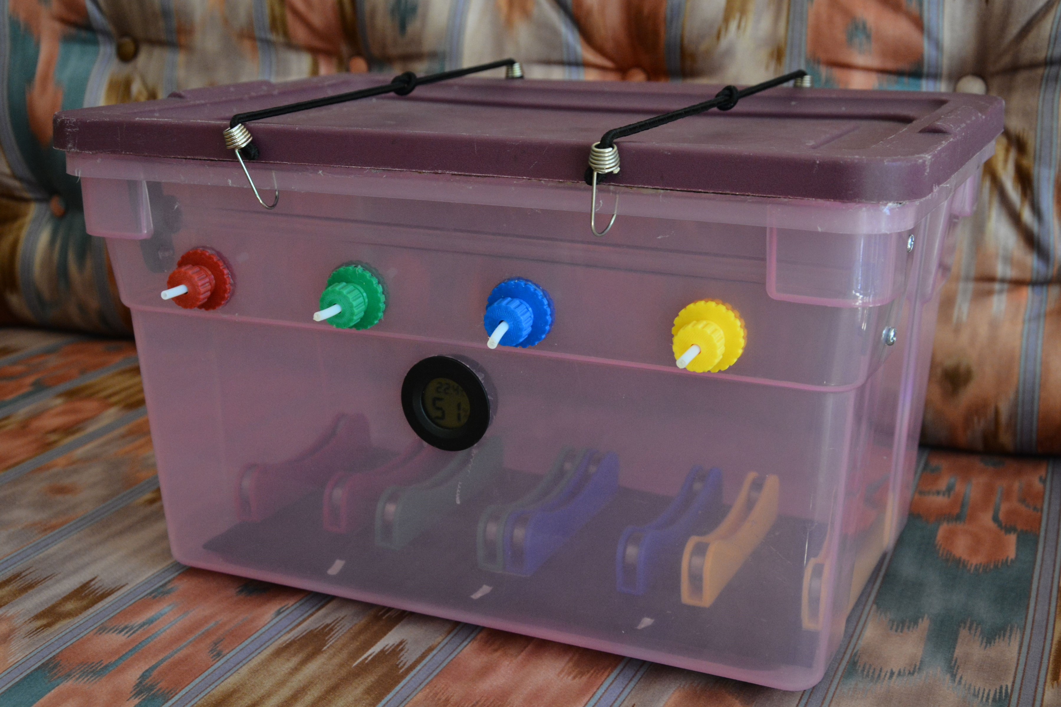
I had a plastic storage box that was not getting much use so I decided to make a dry box. It was large enough to hold four spools of filament.
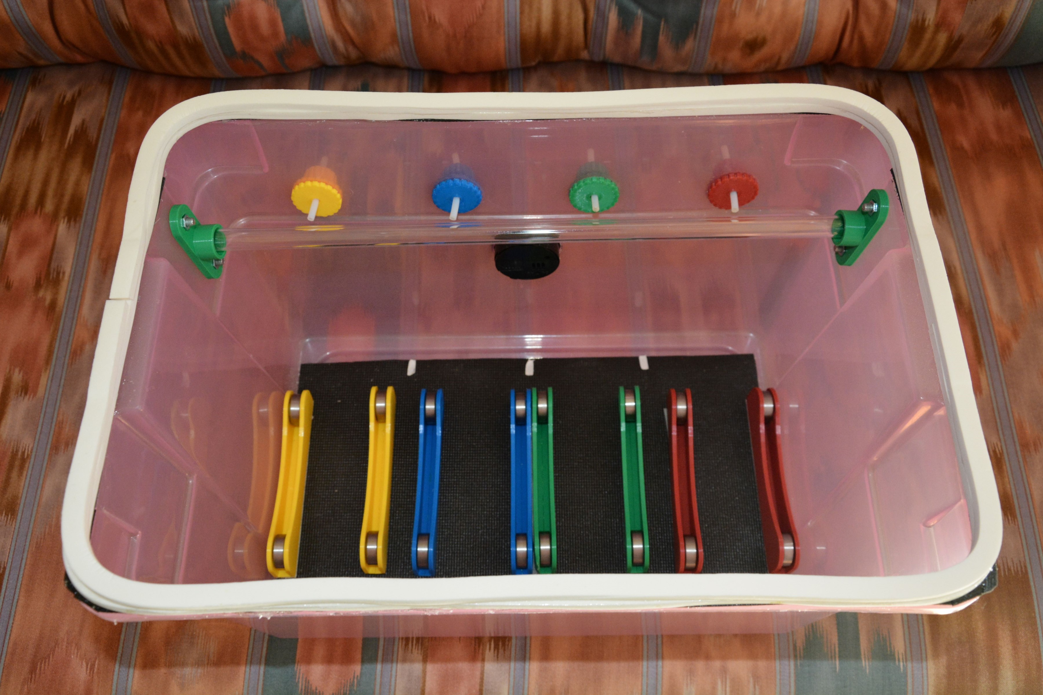
The filament holder is found here: https://www.thingiverse.com/thing:2047554 Each holder requires four 608 bearings that are readily available.
I found that inserting the bearings was not always easy. Heating the plastic with a heat gun allowed me to push the bearings on. This was not the best solution but as I did not want to print them again it was adequate.
The holders were attached to the box floor using double sided tape so their position would stay fixed.
One issue with the filament holder was that the spool would be pulled forward and off the holder when the filament began to run low. To prevent this I printed two pvc pipe mounts found here: https://www.printables.com/model/56008-openscad-pvc-pipe-mount
They were sized for a one half inch acrylic tube I had and positioned so the tube was in front of the spools. The tube kept the spool from being pulled off the holder.
I printed four PTFE tube connectors and installed them on one face of the box. I also installed a temperature/humidity display to indicate what was happening in the box.
Unfortunately, the container was not tall enough to close the top when the spools were in place. This was easily solved with a couple layers foam weather stripping attached to the rim of the container. A couple of small bungee cords hold the top in place.
The drying media used is a large packet of silica gel I had sitting in a desk drawer. The packet had instructions on how to reactivate it: 16 hour at 245°F.
A length of PTFE is used to get the filament from the dry box into the enclosure.
Does It Work?
The enclosure does exactly what it was intended to do and that is to provide a heated environment to help ensure the object being printed stays stuck to the build plate.
The Boo Boo
I measured twice but still messed up. The enclosure was not long enough to accommodate the wiring coming off the back of the build plate. It was so close but no cigar. When attempting to home in the Y direction the wiring would hit the back wall and the stepper motor would keep pushing back and there was this unpleasant hammering. To avoid this resulted in the build plate pushing against the door ever so slightly. I was depressed.
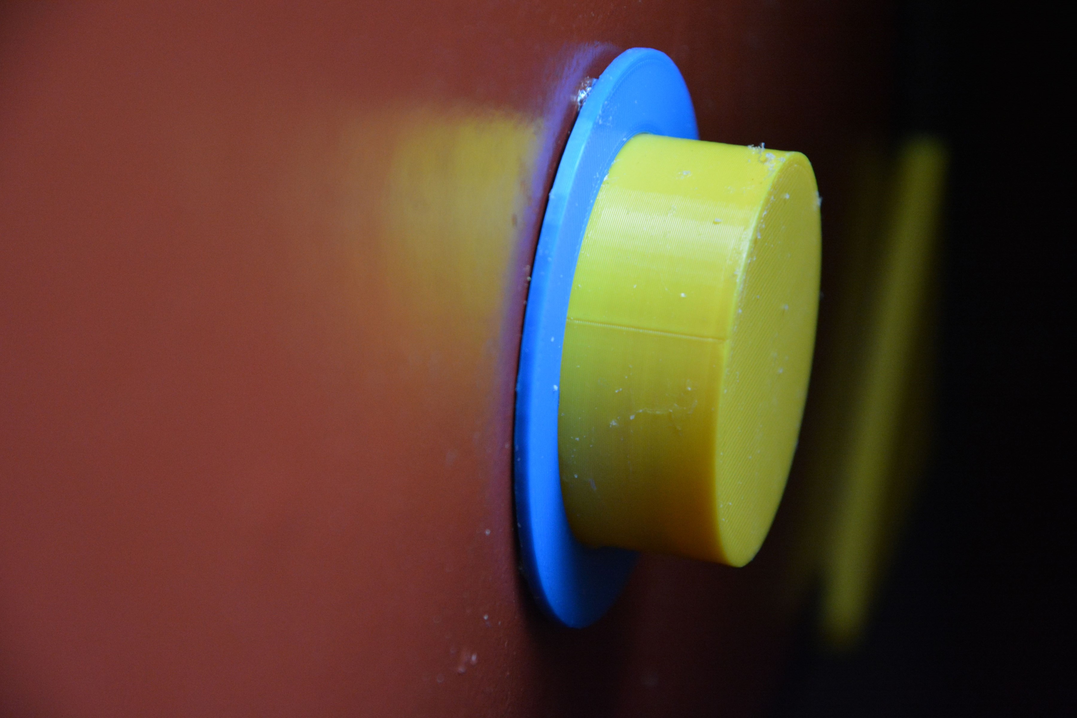
After some time I came up with what I thought was a great solution. I cut a hole in the back wall where the wiring came into contact with it. I then printed and glued a cup to the outside back wall along with big washer. The cup slides into the hole. I then cut a cross in the insulation where the cup was located. Now when the printer is homing the Y axis the wiring just slides through the insulation into the cup and all is fine.
ADDENDUM
Addendum I: Ventilation Fans
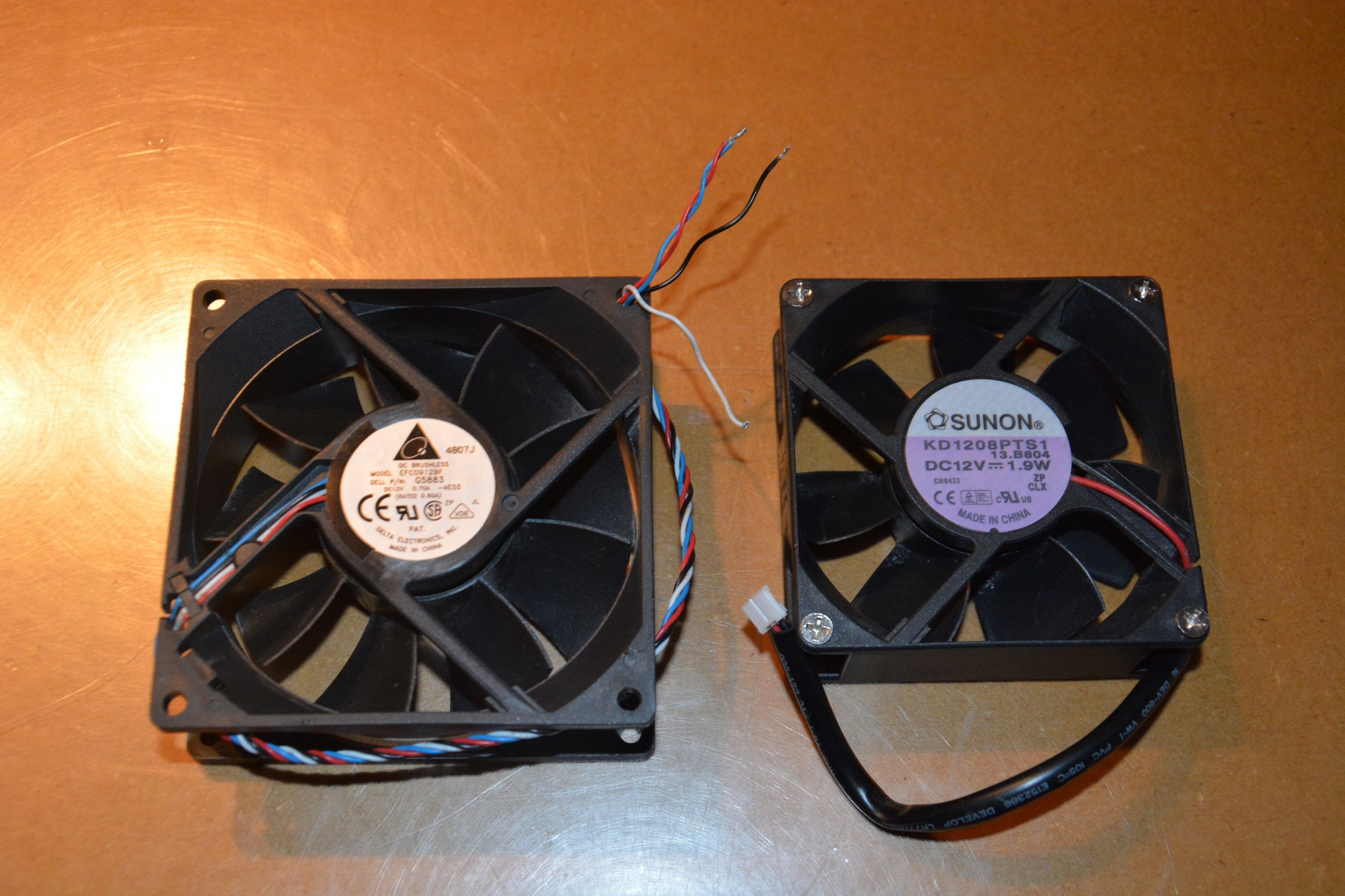
I was repairing a battery pack from an electric scooter and needed a part that I discovered was available from a desktop computer. The local garbage dump has a shed for old electronics and I was able to get an old desktop there. During the dismantling process I discovered it had two cooling fans. After removing them I saw they were rated at 12 Vdc, one for 40 cfm and the other for 80 cfm. The larger fan would be ideal to use as an enclosure cooling fan. It was a 4 wire fan, which meant it had a tachometer output and PWM (Pulse-Width Modulation) input that allowed for speed control. The two remaining wires were for 12 Vdc and GND similar to the smaller fan. To determine the wire designation it is necessary to find the fan specifications as the wire colours will vary between different fans. This took a bit of time as the computer was quite old.
To power the fan I could use a 12 Vdc power adapter that plugs into a wall socket. The adapter should be a regulated power supply. I have found them at a local thrift store for a couple of dollars. You just need to make sure the current rating of the adapter meets the fan current requirement. You can then wire the adapter through a switch to the fan. If you have a 4 wire fan connect the PWM and 12 Vdc wires together and it will run at full speed. If you want to control the speed then purchase an inexpensive PWM speed control module.
If you want to use a temperature controller to operate the fan get one that operates at 12 Vdc. Check its current requirement and ensure the power adapter can supply both the fan and controller.
Another useful item to scavenge from old desktop computers is the power cord. These come in handy when you need to hard wire an AC supply into a device. Just cut off the end, strip the wires and connect them. These cords are 3 wire and have a ground but the same applies to 2 wire extension cords should one be needed.
If you are looking to save a few dollars using a desktop computer cooling fan is the way to go. Try to get a couple of them so you can have a spare if one fails.
Addendum II: Silica Gel Dryer
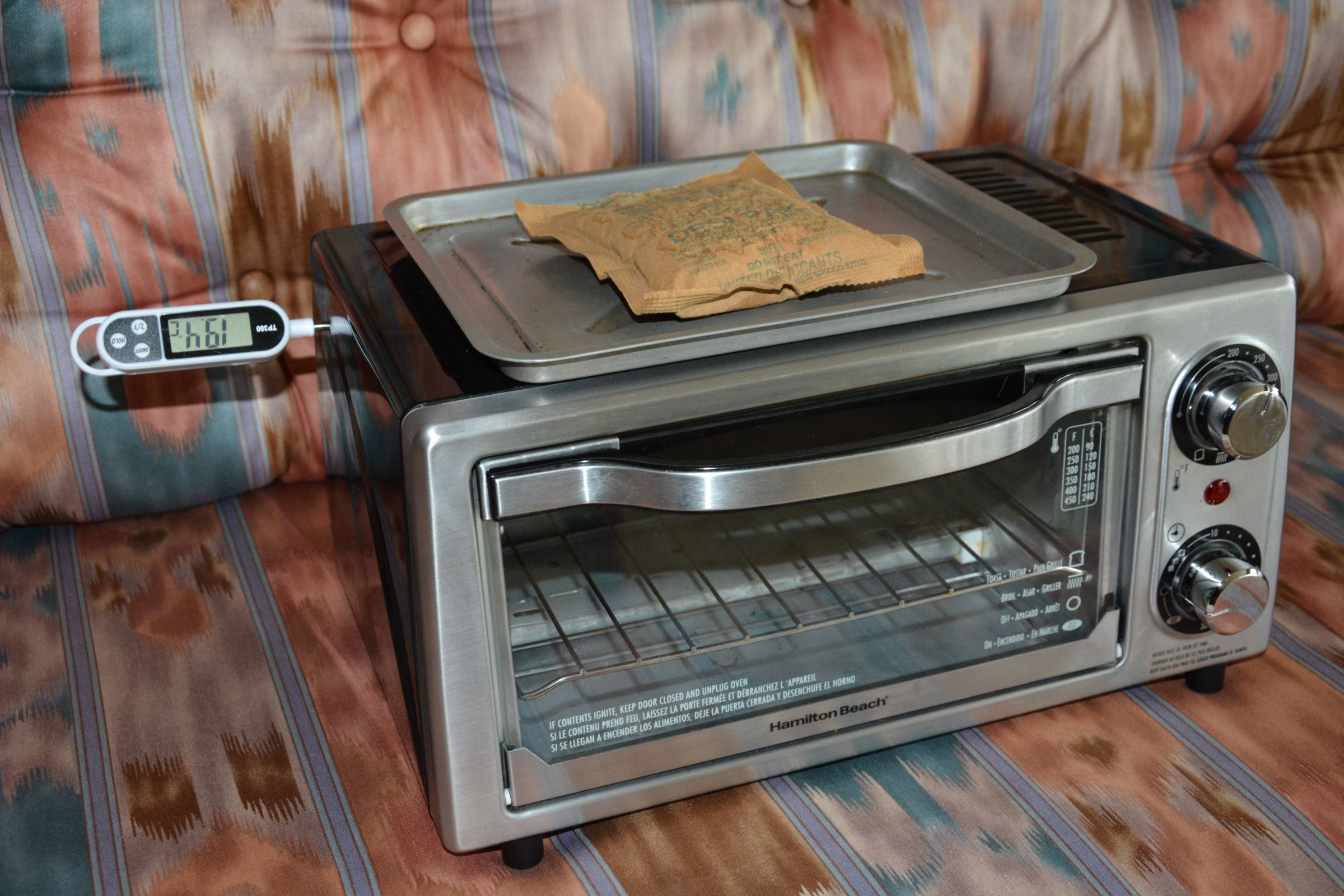
I have a large packet of silica gel that is used in the dry box. This packet can be dried in the oven at 118°C (245°F) for 6 hours to regenerate it. This ties up the oven for a considerable length of time. I found a small toaster oven at a thrift store for just a few dollars. It looked like it had hardly been used so I bought it. I was not sure how accurate the temperature control was so I wanted to install a digital probe thermometer. As there is wiring on both sides of the oven I removed the outer metal case. This involved the simple removal of some screws on the back and bottom of the oven. I was then able to locate a suitable place for the probe far from any wires. I placed it on the side opposite the controls near the top back corner. I replaced the metal case and used the measurements I took to mark the location of the hole. I then drilled a hole through the outer and inner cases. The probe slides easily into the oven and can be removed when the oven is not being used.
Prior to placing the packet in the oven it was preheated to the desired temperature. As I expected, some slight adjustment of the setpoint was needed to get the correct temperature. Six hours later I had a dry packet and the humidity in the dry box is now ~20%.
The oven also had a small pan that can be used to dry loose silica gel should that ever be needed.
CAUTION: Before drilling any holes make sure that you know where all the wires are located!
Addendum III: Fire Proof or Not?
If you are searching for material with which to build an enclosure and have safety in mind you need to be familiar with the following terms.
Combustible: Able to catch fire and burn easily. Examples of non-combustible materials include brick masonry, concrete blocks, hardy backer board, calcium silicate board, cement board, metal, and certain types of glass.
Flammable/Inflammable: Capable of being easily ignited and of burning quickly.
Fireproof: Resistant to damage from fire.
Fire Resistance: Is theproperty of a fire resistant material or assembly to withstand fire or give protection from it.
Fire Retardant: Having the ability or tendency to slow up or halt the spread of fire (as by providing insulation) fire retardant preservatives, fire retardant construction. Fire retardant materials are combustible.
I find the use of some of the terminology confusing but that is just me.
Your basic “fireproof” enclosure could be as follows:
- Enclosure built of metal and or speciality board.
- Any see through areas use fire proof glass.
- If insulated the enclosure is lined with fire brick or high temperature ceramic fibre insulation.
None of these materials are combustible/flammable. But the enclosure will cost a pretty penny.
Any other construction will be a compromise but still the enclosure’s flammability can be limited. Take my enclosure for example.
- Bubble wrap foil insulation is produced with aluminum or metalized polyester and polyethylene (plastic). The material is more prone to melting during a fire, rather than adding to the burning of the structure. It has a Class A (or Class 1) fire rating, which is the best fire rating. The flame spread for a Class A fire rating is 25 or lower, and the smoke development does not exceed a maximum of 450. If the joints do not overlap metal duct tape can be used to seal them.
- MDF (Medium Density Fiberboard) is not fireproof, but it has a level of fire resistance due to its composition. MDF is made from wood fibers and resins that are compressed under high pressure and heat, which creates a dense and solid material that is less flammable than regular wood. However, MDF can still catch fire and burn if exposed to high temperatures for an extended period of time, so it is important to take precautions and treat it with fire retardant products if necessary.
- Plywood burns very easily and is not the best material to use for an enclosure unless it is a fire retardant variety. MDF would have been better but as I did no have enough I went with plywood as it was available.
- Acrylic (plexiglass) is flammable and therefore not suitable for places where high temperatures, open flames or sparks can occur. Acrylic sheet will not immediately burn when exposed to sparks. Sparks will certainly burn in causing the material to smoulder. With acrylic the advantage is that when burned it burns away completely to water vapour and carbon dioxide, completely harmless substances. When burned, it will also hardly form any smoke, the flue gases are completely harmless. Burning acrylic can be extinguished with common extinguishing agents, such as water and foam. Smaller fires, such as flames from burned-in sparks, can normally be blown out like a candle.
Acrylic is used in the construction of many enclosures because of its reasonable cost. Alternatives would be flame resistant acrylic, flame retardant polycarbonate (Lexan) or safety glass.
Do you need to use acrylic sheets on all parts on the enclosure? Sure it looks good but the hazard could be mitigated by limiting it to a single wall such as the door.
In any case, enclosure material selection can be quite involved if you choose it to be. Or you can try to select materials that will mitigate the effects of a fire and limit the use of flammable materials where ever possible.
Addendum IV: Filament Dryer
As soon as filament is removed from its protective packaging, it will begin to absorb moisture from the air. Some filaments do this more quickly than others. At some point the filament will have absorbed enough moisture that it will impact printing and not in a good way. It will then be time to dry the spool of filament
The table below provides a guide to the drying temperature and time for various types of filaments. Drying times may be significantly longer if the moisture content is very high.

The glass transition temperature of various filaments is shown above, which means that it starts to soften from this temperature. The material may deform appreciably in the soft state due to even a small force or even deform due to its own weight. DO NOT exceed this temperature as you can end up with a big blob of filament on the reel. TPU is the exception as it is already soft.
There are various commercial and DIY dryers available with various costs associated with them. One method uses a food dehydrator and that is the method I use as I had purchased one from a thrift store some time ago for less than 10 dollars.
The dehydrator is circular and has multiple trays. It is rated at 120Vac and 550 watts. It has a temperature control dial with a maximum set point of 63°C (145°F). It is adequate for drying TPU, PLA and PETG. Care must be taken not to melt PLA.
I first tried using the dehydrator by placing the filament spool between two trays and wrapping it with plastic food wrap. This was awkward as everything kept moving around. It did work and I was able to dry PLA.
Another method is to cut the centres out of enough trays to provide the vertical space needed for the spool. This ruins the trays for actual food dehydration and so for me this was not something I wanted to do.
I had some bubble wrap foil insulation and foil tape available so I came up with a spacer that can be made for any size of dehydrator.
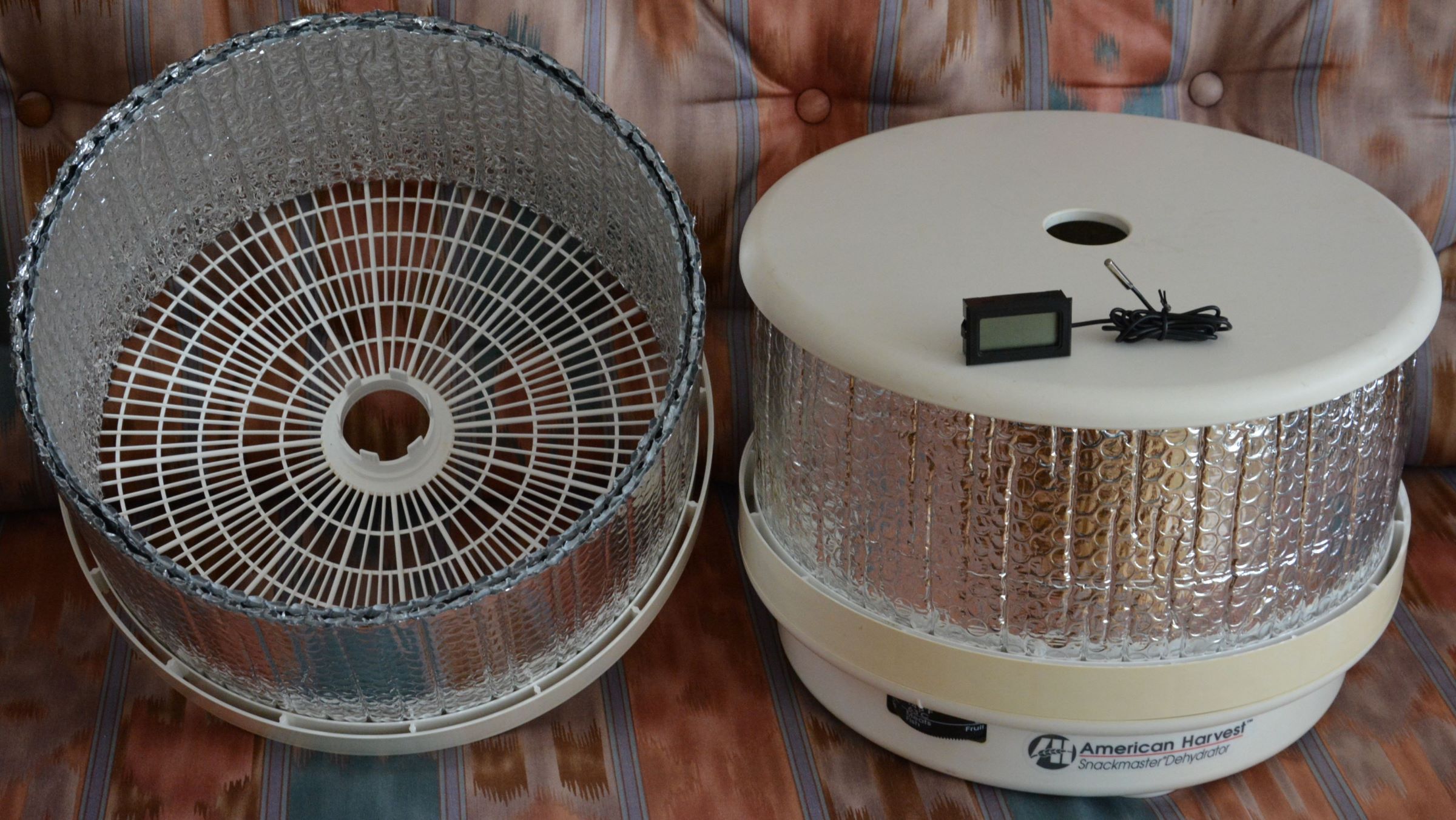
The bubble wrap foil insulation is in a roll 24 inches wide. The spacer is 6 inches tall and will accommodate two filament spools on a tray. For greater rigidity two spacers are used to make one wall. With the 24 inch width it is possible to make two double walled spacers, one for each of two trays. It is possible to dry 1 to 4 filament spools at a time.
To determine the length of the spacer I measured the diameter “d” of the circle where the outer spacer would be located. I then calculated the circumference “C” of this circle: C=pi x d=3.14 x d. I added little extra to make sure as I would be trimming the spacers to length. The inner space will be shorter but I kept it the same length to make cutting easier. Four spacers were cut from a single length of insulation.
Before continuing 4 strips of 6 inch metal tape were cut. As the tape is 2 inches wide they were cut in half length wise to make 8 strips of tape 1 inch wide and 6 inches long. These were used to tape the butt end joints of the spacers on both sides.
The outer spacer wall was placed in position in one of the trays making sure it was snug against the tray’s rim. The excess overlapping insulation was marked and cut off. Both sides of the butt end joint were taped using the metal tape strips. To make it easier the back of the joint was taped with painter’s tape to ensure good alignment. After taping the front of the joint the painter’s tape was removed and the back of the joint was taped.
The outer spacer wall was put back in position on the tray. The inner spacer wall was placed inside the outer spacer wall and the process used on the outer spacer wall was repeated. In this case a snug fit between the two spacer walls is needed.
Once completed the inner spacer wall is inserted into the outer spacer wall and the spacer is complete.
It was not known how accurately the temperature dial controls the temperature. I used a humidity/temperature display to ensure the temperature would not go too high. The display is placed on the outlet of the dehydrator located on the top of the dehydrator. This would provide a humidity reading of the air exiting the dehydrator. The temperature sensor has a long lead and can be placed anywhere inside the dehydrator to provide a display of the temperature. By starting at a lower temperature the dehydrator set point can be raised until the desired temperature is reached.
Addendum V: Filament Storage
After using a particular filament it is a good idea to store it in some manner to prevent it from absorbing moisture. If you have a dry box that will work but it may not be large enough for all the spools you may have. Another storage method is required.
I purchased some large format double zipper sealed plastic storage bags. The box contained 13 bags that are 10-9/16 inches x 11 inches (26.8cm x 27.9cm) in size. A filament spool fits nicely into one of these bags.
At some point in the past I had purchased a USB powered vacuum that is intended to be used for cleaning keyboards. It came with both a brush and a rubber nozzle. The rubber nozzle is what I use. This vacuum is available from AliExpress for well under ten dollars.
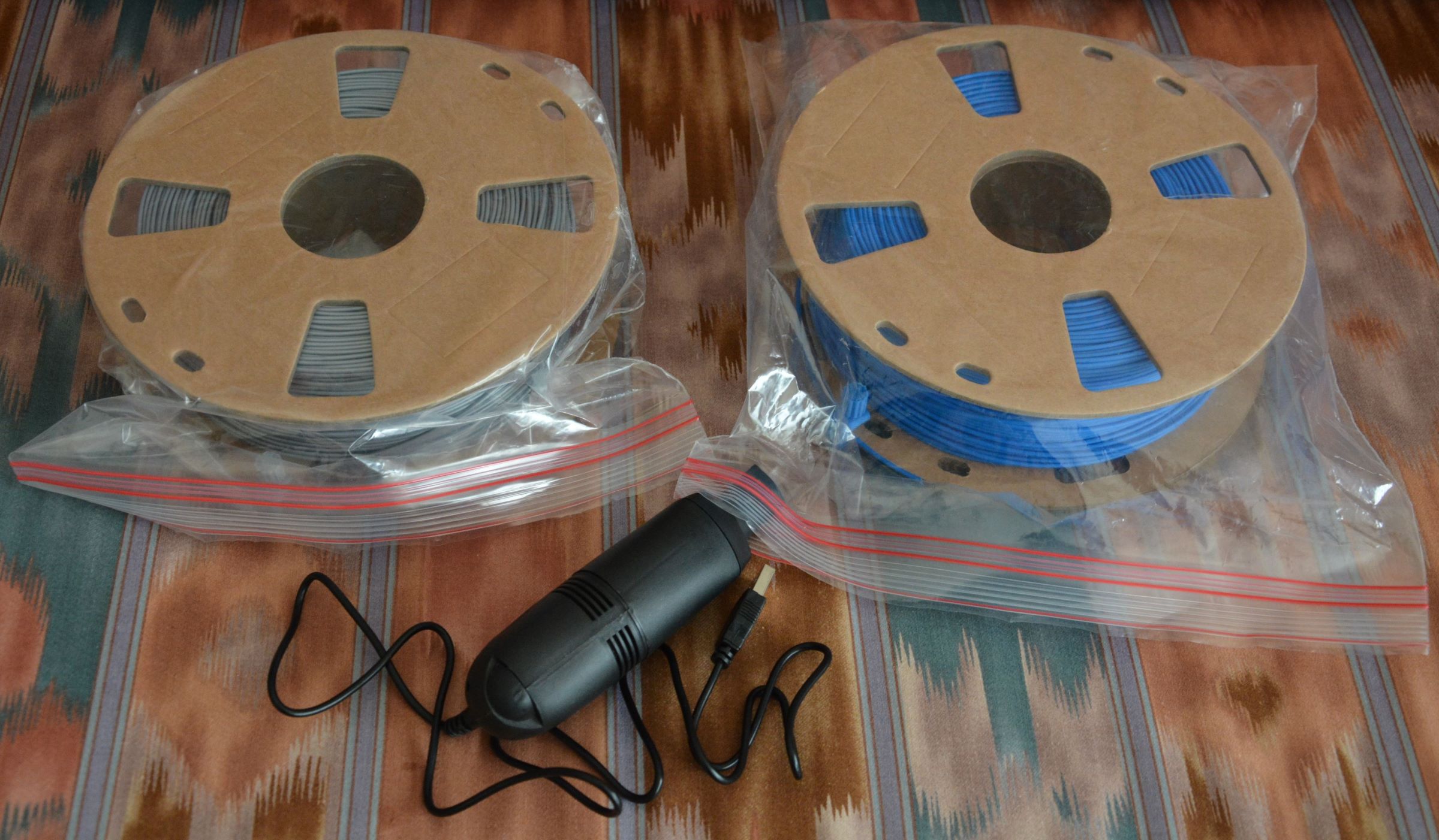
The filament spool is placed inside the storage bag along with a packet of silica gel. Both zippers are closed leaving only enough space at one end for the vacuum nozzle. The vacuum will suck out the air in a matter of seconds. Still running the vacuum is pulled back until the nozzle clears the inner zipper. The inner zipper is closed sealing the bag. The vacuum is removed and the outer zipper is closed.
It’s just that easy!