Build a Supercapacitor Powered Speaker!
by JGJMatt in Workshop > 3D Printing
31283 Views, 292 Favorites, 0 Comments
Build a Supercapacitor Powered Speaker!
.png)
.gif)


Hello fellow makers,
We are currently experiencing a massive energy crises in South Africa where we are left without any electricity for 4 hour intervals throughout the day during a nationally implemented "loadshedding".
As a result there is a requirement for energy saving and green energy devices.
I started working on this project back in 2022 and had the PCB custom made and assembled by JLCPCB in order to use very high efficiency components.
With the current setup I get a minimum of 6 hours playtime from a full charge without solar, this is thanks to the TPA2013D1 class D amplifier that has 87.5%+ efficiency and a built in boost converter that keeps a constant 5.5V even as the supercapacitors deplete.
If the speaker is placed in a sunny windowsill or outdoors so that the solar panel is in the sun there is absolutely no voltage sag on the supercapacitor when listening at maximum volume.
If you enjoy my Instructables and would like to support my future projects you can Buy Me A Coffee.
What You Will Need:

To make your own you will need the following:
- Custom made PCB by JLCPCB
Gerber file available at - Google Drive

- Access to a 3D printer
Amazon - Creality Ender 3 3D Printer
- PETG or ABS filament
Amazon - eSUN PETG Filament 1.75mm
- TPU filament
Amazon - OVERTURE TPU Filament 1.75mm Flexible
- 3in Full range speaker
Amazon - Dayton Audio 3" Full-Range Driver 8 Ohm
- Speaker cloth
- 60mm X 90mm 5V Solar panel
Amazon - 60mm x 90mm 5V 150mA Poly Mini Solar Cell
- B-6000 Glue
Amazon - B6000 Jewelry Glue Clear
- 8mm M4 Screws
Amazon - M4 x 8MM Socket Head Cap Screws,304 Stainless Steel
Optional:
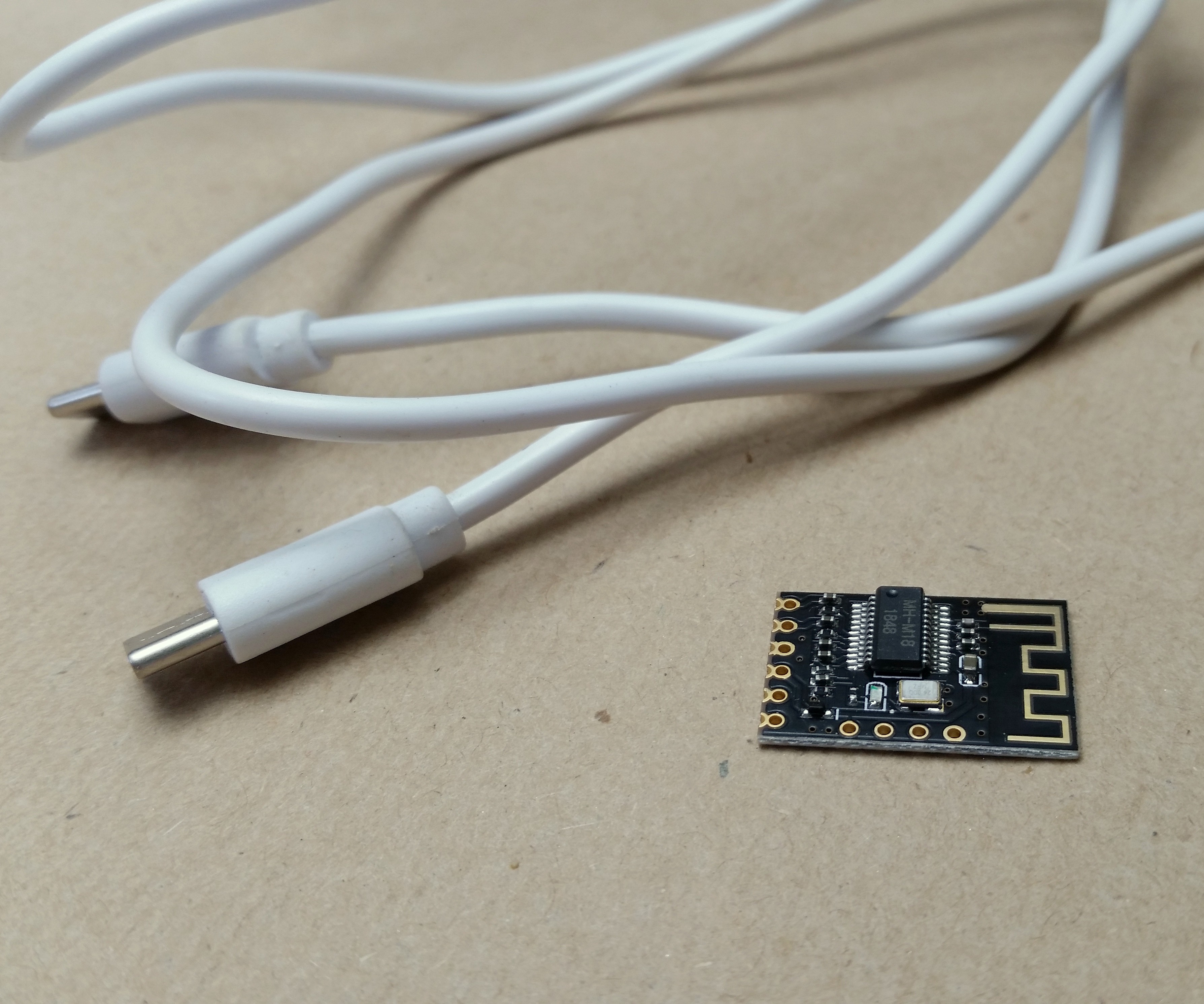
- MH-M18 Bluetooth module
Amazon - M18 Wireless Bluetooth MP3 Audio Receiver Board
- USB-C Cable
- Spray paint
- Filler primer
Amazon - Rust-Oleum Filler & Sandable Primer
- Body filler
- Polyfill
Amazon - Fairfield The Original Fil Polyester Poly-Fill
- PVA foam/Felt pads
Amazon - Black Self Adhesive Felt Bumpers 1/2" Diameter and 1/8" Thick
*As an Amazon Associate I receive a small percentage from sales made through provided links at no cost to you, this helps fund future projects.
The Mainboard:


The circuit is designed around two 400 Farad supercapacitors that are in series giving us a working voltage of 5.4 volts and 200 Farad capacitance when fully charged. To protect the supercapacitors from overcharging as well as to keep the two balanced I added a protection circuit using the old trusted TL431 IC to each capacitor in order to keep each below the 2.7V maximum rating.
Unfortunately unlike lithium batteries with supercapacitors the voltage drop is linear as it depletes, to counter this we need a boost converter to keep the output voltage stable otherwise the output of the audio amplifier will quickly drop and stop working once it reaches it's minimum rated voltage.

Luckily we get amazing chips like the TPA2013D1 that has a built in boost converter with an operating voltage of 1.8V to 5.5V and also the boost circuit gets disengaged when our supercapacitors are fully charged making even more efficient.
I added a USB-C for charging from an adaptor if you are in a hurry any the capacitors are depleted.
The USB-C is also wired for analogue audio input which enables audio to be played over the USB cable when plugged into the USB-C port on your laptop/desktop while also charging the capacitors.
I ordered SMD assembled PCB's from JLCPCB to test the concept and received the finished boards within two weeks.

Why Not Just Use Batteries?
There are so many reasons supercapacitors are much better suited for low power applications like this, most modern 18650 batteries have a typical cycle life of 300 - 500 (charge, discharge cycles) whereas supercapacitors have 100000 to a million life cycles!
That means the performance of the capacitor will not degrade over the products lifespan like li-ion and in turn we get a product with a MUCH longer lifespan.
Then there is the quick charging, if your power source is capable of high currents we can literally charge a product fully in seconds.
Design and Print:


All the enclosure components are designed with Fusion 360 and I have included all the files necessary and also the design files so you can alter it to your needs.
To keep the part list needed down all the components are 3D printed this includes a fully 3D printed passive radiator with TPU filament to aid with the low frequencies.


The enclosure is printed in PETG to handle the sun exposure needed for the solar panel and was designed so that it does not require any supports in order to use the absolute minimum material with no waste.
Refine the Print:


To give the enclosure a more premium look I sanded the entire box with some 80 grit sanding paper to get rid of any imperfections before applying Bondo filler before priming the case.


After sanding the primer smooth with 400 grit sanding paper wetted with soapy water I wiped all the parts clean and applied matt graphite gray paint to all of the main components and a matt gold to the front bezel.

The Printed Passive Radiator:


Next I started by assembling the passive radiator, I use B-6000 glue for all of the assembling as it is an excellent adhesive but also remains slightly rubbery which will give us a great airtight seal which is very important for the best possible sound quality.

When the centre cap of the passive radiator is printed with 30% cubic infill and no bottom layers you can use 6mm M4 screws to adjust the weight/frequency of the passive radiator.

Install the Solar Panel:

With the passive radiator adhered to the back frame of the enclosure we can install the solar panel next.

The solar panel is a 60mm X 90mm 5V cell. Using the same B-6000 glue add a thick bead around the indent of the solar cell in the enclosures back frame and press the solar panel into place.

Assemble the Speaker:


Now we can move on to the front frame of the enclosure, here we will first adhere the speaker driver into place.
The driver I'm using is a 3in Bose full range driver salvaged from a Mercedes and has incredible sound for its size however the mounting hole should work with most 3in round drivers without modifications.

To complete the front frame we simply need to attach the wires from the speaker to the speaker output of the amplifier board and screw the PCB into place with with 3mm self tapping screws onto the mounting holes in the enclosure.
Before pressing the two enclosure shells together I loosely stuff the inside with low density polyfill.

Make sure your solar panel is plugged into the board before closing.

I add a bead of B-6000 glue around the inside of the edge of the enclosure before pressing the two halves together to ensure an airtight seal.
To finish off the aesthetics of the prototype I covered the front mesh in black speaker cloth before inserting it into the bezel and attaching it to the front of the enclosure.


Add the Finishing Touches:


After finishing the speaker it looked a little boring so I quickly printed a badge for the front mesh, sprayed it in the same matt gold and attached it to the front.

I also cut out some non slip pads for the bottom on my laser cutter from 2mm PVA foam.

Updates:
Bluetooth:
With the runtime of the speaker far exceeding my expectations I decided to see if adding a Bluetooth receiver would be viable.
Because the USB-C charging port on the speaker is also wired to receive analogue signal input we can use the port to both power a Bluetooth module as well as receive the signal.
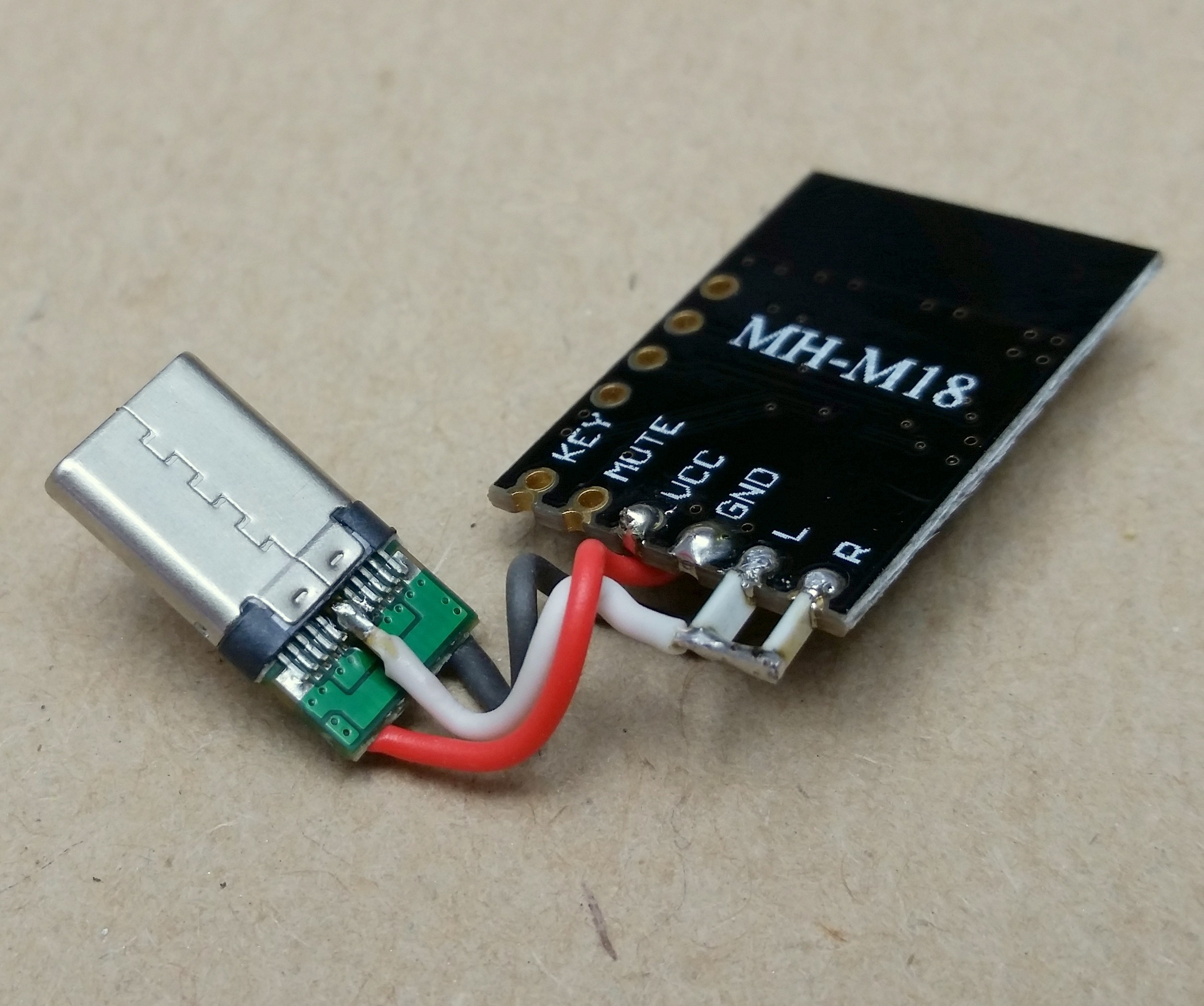
Using a spare USB-C cable as a donor for a plug and a Bluetooth 5.0 MH-M18 module we can create a simple dongle.
The stereo output of the Bluetooth module is made mono by using two 150ohm resistors, the output is then soldered onto the DP1/2 and DN1/2 pins of the USB-C plug, VCC and GND have dedicated pads on most connectors.
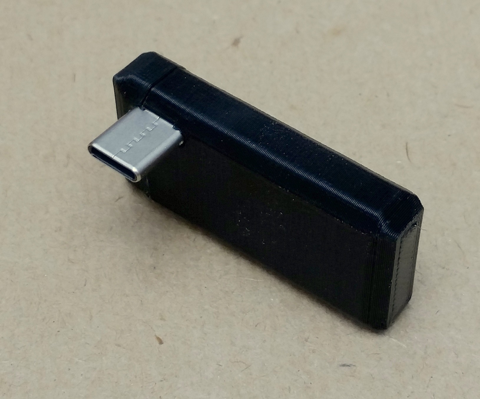
The board is then simply placed in a simple 3D printed cover.
- - -
The future of this project:
My next step for this project is to design a speaker driver that can be 3D printed, this will enable me to produce kits with the electronic components along with STL files for all the components needed to build your own battery-less portable speaker.
Not only would this be a way to easily get the tech out there as shipping would be a lot easier and more affordable but I also believe this to be a great STEM project for students as it combines so many different learning elements.
- - -
First prototype of a 3D printed driver:
I started work on a replacement for the regular speaker driver with a completely DIY driver.

At the moment I am testing out the voice coil design and then once that has been finalised I will move on to the magnet housing.
First tests of the voice coil sounded very promising but I will need to alter the design in order to fit more windings as they are currently only 2ohms and I don't want to decrease the wire gauge to keep assembly for children easier.
Enjoy!

I hope you guys find this Instructable useful and if you have any questions please feel free to leave me a message or comment bellow.
Thank you for taking the time to read through my project and as always..
Happy making!


