Blynk IoT | IoT Platform Series #1
by Common9899 in Circuits > Software
1042 Views, 0 Favorites, 0 Comments
Blynk IoT | IoT Platform Series #1

Hey, what's up, Guys! Akarsh here from CETech.
For all the IoT makers and newbies, we very well know and understand the Blynk IoT Platform and how to use the Blynk 1.0 (Legacy version). But as Blynk has upgraded to Blynk 2.0 there were many changes made in the new documentation which are not yet noted or maybe missed out.
This article points to understanding and implementing not only the Dashboard usage of both Blynk 1.0 and 2.0 but also all the API endpoints that make its usage of it functional.
Supplies
Get PCBs for Your Projects Manufactured
You must check out PCBWAY for ordering PCBs online for cheap!
You get 10 good-quality PCBs manufactured and shipped to your doorstep for cheap. You will also get a discount on shipping on your first order. Upload your Gerber files onto PCBWAY to get them manufactured with good quality and quick turnaround time. PCBWay now could provide a complete product solution, from design to enclosure production. Check out their online Gerber viewer function. With reward points, you can get free stuff from their gift shop.
About Blynk
Before getting started, let us understand what is Blynk (For beginners)
Blynk is a full suite of software required to prototype, deploy, and remotely manage connected electronic devices at any scale: from personal IoT projects to millions of commercial connected products.
The above text is an official statement/description of what Blynk is, and what it serves as a solution for the General Public as a tool.
Think about a Plug-and-Play IoT Platform for IoT Developers, to build and develop IoT applications on the go. Blynk is the same, with easy-to-make buttons, visualization charts, and many more from it.
The ability to use drag-and-drop widgets has made the IoT Platform grow even more. In only a matter of seconds, we can control our Wireless Board from the Web Dashboard, as well as Mobile App.
Blynk 1.0 (Inactive)
Back in 2016, when Blynk introduced multiple features like the ability to use the Library file and directly connect any WiFi-enabled board to the Blynk Cloud. Since then the Cloud was LIVE and had a pretty decent latency. Which caught the attention of many IoT developers or learners. It was during this period of time when people started building many projects on this platform and the world of IoT became a thing for people.
Since then Blynk started documenting all the procedures, and steps required to use their platform. But recently with the upcoming Blynk 2.0, the documentation will soon be removed which is currently hosted on http://docs.blynk.cc. Even though not ACTIVE, the Blynk cloud for those API requests is still LIVE.
API Request - Send/Receive information to/from the Blynk Cloud, to/from the Device with Blynk Code.
To get started, it is required to first Download the Blynk App (LEGACY) (No more available on the App store as per the information here)

After downloading, it is necessary to have a Facebook Account to be able to Sign In/ Login to the Blynk App.
From this App, with each new project, we are provided with an Auth Token which we can use to access the Blynk Cloud and its services. We can either use the App to control/monitor our Wireless devices or the Auth Token to access the LIVE data using API requests.
1. Using Blynk App
Open App > New Project > Enter 'Project name' and Choose Device > click Create
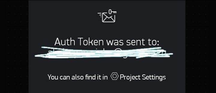
Most likely, the Auth Token is sent to the Email ID associated automatically during the creation of a 'new project'. Check Mail if prompted, else Click on Settings (gear icon on the top bar) and scroll down to Copy the Auth Token.
1 / 2
Now that we have the Auth Token, let us know about the Widgets available on this App. Tap and hold the Widget to drag it to the new position.

Each Widget has its own settings. Tap on the widget to get to them to view the settings
INPUT/OUTPUT - Select a Digital pin only if you'll be using the specific pin at all times. Any changes in the code will require to be adjusted in the app as well. For ease of purpose, we use a Virtual pin, since it gives the flexibility to choose the hardware pin from the code itself.
The rest of the settings depend on the widget we choose. For this project, we shall use 1 Button and 1 Value Display widget to showcase control and monitor
Let us add both widgets to the Panel.
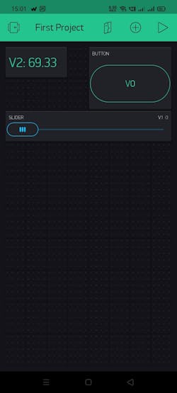
Provide the below configurations accordingly,
Button -> OUTPUT - V0 (0-1), Mode - SWITCH
Slider -> OUTPUT - V1 (0-1023), Decimals-AUTO, SOR&SV-ON
Value Display -> Value - V2 (0-1023), Reading rate - PUSH
Great! Now RUN the Project
(Code) Blynk 1.0
- In the code, WiFi.h, WiFiClient.h, Wire.h, SparkFunBME280.h, and BlynkSimpleEsp32.h (download here) libraries have been used.
- Replace <wifi_name>, <password>, and auth_token under SSID, password, and auth with your WiFi and Blynk credentials. (Hint - Check the settings of the Project in the App for Auth)
In the Arduino IDE, navigate to Sketch > Include Library > Add .ZIP Library. At the top of the drop-down list, select the option to "Add .ZIP Library''. Then browse to the downloaded ZIP file of BlynkSimpleEsp32
I will be using the BME280 sensor to send temperature data to the Blynk Cloud, I will share a commented code that can be used to share dummy data as well.
#define BLYNK_PRINT Serial

long randNumber; float flrandNumber;

#include <WiFi.h>
#include <WiFiClient.h>
#include <BlynkSimpleEsp32.h>
#include <Wire.h>
#include "SparkFunBME280.h"
int freq = 2000;
int channel = 0;
int resolution = 8;
BlynkTimer timer;
BME280 bme;

String temperature;

char auth[] = "<auth_token>";       /* You should get Auth Token in the Blynk App. */
char ssid[] = "<wifi_name>";                    /* Your Wi-Fi Credentials */
char pass[] = "<password>";

void setup() {
    pinMode(2, OUTPUT);
    ledcSetup(channel, freq, resolution);
    ledcAttachPin(4, channel);
    Serial.begin(9600);
    Serial.println("WiFi connected");
    Blynk.begin(auth, ssid, pass);
    Wire.begin();
    if (bme.beginI2C() == false) /* Begin communication over I2C */
    {
        Serial.println("The sensor did not respond. Please check wiring.");
        while(1); /* Freeze */
    }
    timer.setInterval(1000L, myTimerEvent);
}
BLYNK_WRITE(V0)
{  /* This function gets called each time something changes on the widget */
    int value = param.asInt();  /* This gets the 'value' of the Widget as an integer */
    digitalWrite(2,value);
    Serial.print("Pin 2 - ");
    Serial.println(value);
}
BLYNK_WRITE(V1)
{  /* This function gets called each time something changes on the widget */
    int value2 = param.asInt();  /* This gets the 'value' of the Widget as an integer */
    /*map(value2, 0, 255, 0, 255) */
    ledcWrite(channel, value2);
    Serial.print("Pin 4 - ");
    Serial.println(value2);
}
void myTimerEvent()
{
    Blynk.virtualWrite(V2, bme.readFloatHumidity());

    /*randNumber = random(600, 800);
    flrandNumber = (float)randNumber / 100.00;
    Blynk.virtualWrite(V2, flrandNumber); */

}
void loop(){
    Blynk.run();
    timer.run();
}
Now, let us use API to monitor and control the virtual pins.
(API) Blynk 1.0 - Inactive
Even though the API documentation of Blynk 1.0 is no longer managed, the servers are still functional. The server will be alive till December 2022 as per the information here
HTTP Endpoint (Bangalore Server) - https://blr1.blynk.cloud/external/api
Parameters - token and pins
Sample UPDATE and GET requests
1. Control the Virtual Pins (Send data to the Dev board)
https://blynk.cloud/external/api/update?token=<auth_token>&v1=100
2. View the Data on the Dev board with Virtual Pin
https://blynk.cloud/external/api/get?token=<auth_token>&v0
Blynk 2.0 (2021) - Active
In May 2021, Blynk released the latest generation of the Blynk IoT Platform called “Blynk IoT”. This guide is intended to assist someone currently using the legacy version of Blynk (“Blynk Legacy”) to migrate to the latest Blynk system.
Features of Blynk -
- Blynk.App: a unique, no-code mobile app builder for IoT
- Blynk.360: a web console to manage devices, users, and data
- Templates: new device creation process designed for scale
- Blynk.Inject: a WI-FI manager built into the Blynk mobile app
- Blynk.Air: over-the-air firmware updates
- All kinds of Automations (think Eventor on steroids)
- Voice assistants and much much more
To get started, it is required to signup and login to the Blynk Cloud.

Next, click on Templates from the left side panel, and create a New Template with the below configurations.

After clicking on the created template, we should our Template ID and Device Name as our Firmware configurations. Make sure to note where to find them 😉

Next, we need to Add DataStreams which would work like a bucket where we can store data in the cloud for streaming across from the Device to/from the cloud.
Click on the Edit button in the top-right section, click on Datastreams and create New DataStream > Virtual Pin. Then use the below configurations -
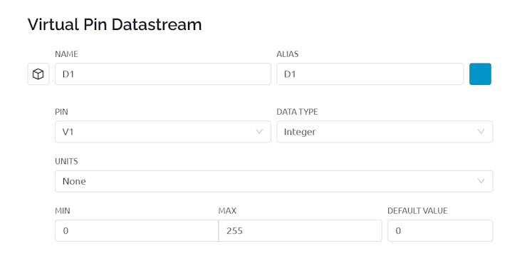
Make changes accordingly, like using a double data type for decimal value, or selecting another virtual pin.
Similarly, create another data stream with MIN 0 and MAX 1.
Next on the Automations tab, Select the type of automation as a sensor for min-max 0-155 and switch for 0-1.

Now, let us add widgets on the Web Dashboard to monitor and control the Datastreams.
Double-click on Switch and Label Display from the Widget Box to add them to the Dashboard panel. Next, click on the gear button of each and select the appropriate Datastream you are using.

1 / 3
That's it on the Templates section! Click on Save and Apply and head to the Devices. Click on the Search icon on the left-side panel to open the Device Dashboard section. Here, first Add New Device > from Templates > Choose the Template we just created.
We should see our Dashboard now -
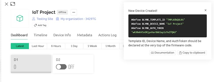
Notice that all the device configurations are now ready to be copied for the Hardware device code.
(Code) Blynk 2.0
In your Arduino IDE, go to Sketch > Include Library > Manage Libraries and search for 'Blynk'. The top-most result should be the library we require. To confirm, check if the latest version matches the one on Github.
Now, use the below code to get started and use the Blynk Cloud.
#define BLYNK_TEMPLATE_ID " "
#define BLYNK_DEVICE_NAME " "
#define BLYNK_AUTH_TOKEN " "
char ssid[] = " ";                    /* Your Wi-Fi Credentials */
char pass[] = " ";

#define BLYNK_FIRMWARE_VERSION        "1.1.0"
#define BLYNK_PRINT Serial

#define APP_DEBUG

#include <Wire.h>
#include "SparkFunBME280.h"
#include "BlynkSimpleEsp32.h"

int freq = 2000;
int channel = 0;
int resolution = 8;

long randNumber; float flrandNumber;
BlynkTimer timer;
BME280 bme;

#define BLYNK_PRINT Serial
//#define BLYNK_DEBUG
#define APP_DEBUG
#define USE_WROVER_BOARD

String temperature;

void myTimerEvent()
{
  Blynk.virtualWrite(V0, bme.readFloatHumidity());

    /*randNumber = random(600, 800);
    flrandNumber = (float)randNumber / 10.0;
    Blynk.virtualWrite(V0, flrandNumber); */
}

BLYNK_WRITE(V1)
{
  int pinValue = param.asInt(); /* assigning incoming value from pin V1 to a variable*/
  digitalWrite(2,pinValue);

  /*Serial.print("Pin 2 - ");
  Serial.println(pinValue);*/
}

void setup()
{
  Serial.begin(115200);
  delay(100);

  pinMode(2, OUTPUT);
    ledcSetup(channel, freq, resolution);
    ledcAttachPin(4, channel);


   Blynk.begin(BLYNK_AUTH_TOKEN, ssid, pass);

  Wire.begin();
    if (bme.beginI2C() == false) /* Begin communication over I2C */
    {
        Serial.println("The sensor did not respond. Please check wiring.");
        while(1); /* Freeze */
    }
  timer.setInterval(1000L, myTimerEvent);
}

void loop() {
  Blynk.run();
  timer.run();
}
After everything, Compile and Upload the code to the ESP32. Now, open the Serial monitor to check if there is any error. If not, the monitor shall look like this once connected to the Blynk Cloud with the Device created.
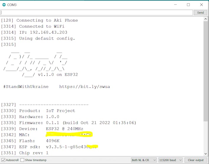
Below DashBoard is an example of how it looks.

Now, let us use API to monitor and control the virtual pins.
(API) Blynk 2.0
The REST APIs of Blynk 2.0 is the same to use as it was with the Legacy version. The Latest API documentation is available on HTTPs REST API for Blynk.Cloud. And below is only an example of how to implement it.
HTTP Endpoint - https://blynk.cloud/external/api
Parameters - token, pin, value, etc.
Sample UPDATE and GET requests
1. Control the Virtual Pins (Send data to the Dev board)
https://blynk.cloud/external/api/update?token=<auth_token>&v1=100
2. View the Data on the Dev board with Virtual Pin
https://blynk.cloud/external/api/get?token=<auth_token>&v0
Blynk.Edgent
With Blynk 2.0, which includes many features as listed. Another feature is also present, which allows for a reduction in uploading code when a change in the network is observed frequently. Uploading a new code to the Board without having to reconnect to a PC, using the Edgent OTA feature.
It comes with the OTA feature, allowing us to update the code from the cloud itself. Let us see how to use this feature -
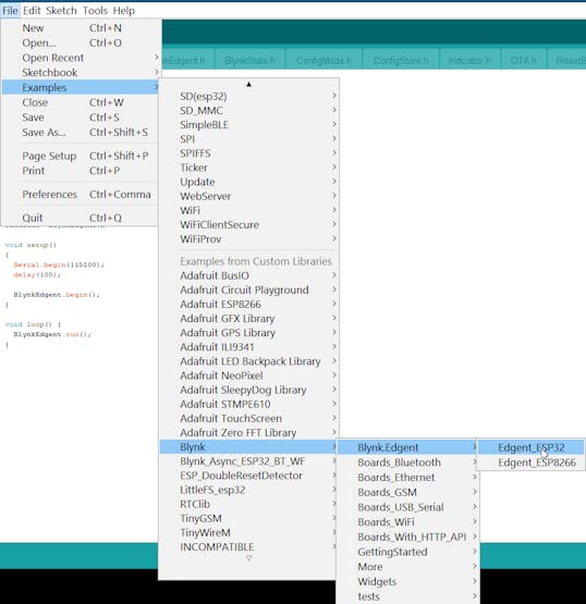
We can directly get started with the Example provided by them. In the Arduino IDE, navigate to Files > Examples > Blynk > Blynk.Edgent > Edgent_ESP32 - It will open the default code.
Here, only make the changes in the Edgent_ESP32.h file, like adding Virtual Pins to be controlled or monitored, widget properties, timers, etc. Below is an example -
#define BLYNK_TEMPLATE_ID " "
#define BLYNK_DEVICE_NAME " "
#define BLYNK_AUTH_TOKEN " "

#define BLYNK_FIRMWARE_VERSION        "0.1.1"
#define BLYNK_PRINT Serial

#define APP_DEBUG

#include <Wire.h>
#include "SparkFunBME280.h"

#include "BlynkEdgent.h"

int freq = 2000;
int channel = 0;
int resolution = 8;

long randNumber; float flrandNumber;
BME280 bme;

#define BLYNK_PRINT Serial
/* #define BLYNK_DEBUG */
#define APP_DEBUG
#define USE_WROVER_BOARD

String temperature;

void myTimerEvent()
{
  Blynk.virtualWrite(V0, bme.readFloatHumidity());

    /* randNumber = random(600, 800);
    flrandNumber = (float)randNumber / 100.00;
    Blynk.virtualWrite(V2, flrandNumber); */
}

BLYNK_WRITE(V1)
{
  int pinValue = param.asInt(); // assigning incoming value from pin V1 to a variable
  digitalWrite(2,pinValue);
}

void setup()
{
  Serial.begin(115200);
  delay(100);

  pinMode(2, OUTPUT);

  BlynkEdgent.begin();
  Wire.begin();
    if (bme.beginI2C() == false) /* Begin communication over I2C */
    {
        Serial.println("The sensor did not respond. Please check wiring.");
        while(1); /* Freeze */
    }
  timer.setInterval(1000L, myTimerEvent);
}

void loop() {
  BlynkEdgent.run();
}
Compile and Upload the code to ESP32 Dev Board and open the serial monitor.

The console will show this if the board was previously linked with the cloud. Skip the Blynk App section if true.
Make sure the template, virtual pins, and datastream are linked to the template. Post that, we're good to go.

We shall now connect our Mobile to the Dev Board'swifi Hotspot.
Blynk.App
After connecting to the Dev Board's wifi hotspot, follow the below steps to provide the WiFi credentials to the Dev Board. It saves the information on the file system of the board, which remains saved till the time we initiate to change it again.
1. Open Blynk App
2. Open the MENU icon in the upper right corner In the upper right corner
3. Tap on + Add New Device
4. The app will scan the WiFi networks around you and offer to connect to your device. In our example, the device name will be: [name]
5. Once the connection is established, the Blynk app will guide us through the provisioning process. Like entering the WiFi name and Password. (One-time process for single wifi usage)

We can test it using the API -
https://blr1.blynk.cloud/external/api/update?token=<auth_token>&v1=1
The LED will turn ON hopefully. And with v1=0, it will turn OFF.
Let us now get ahead with using the OTA feature with this.
Blynk.Air
In the Blynk Cloud, open Blynk.Air on the left-side panel > Click New Shipping > Specify Target Selection.

Now, let's make changes to the edgent's initial code (Arduino IDE), to view the changes after OTA.

The same must be updated on the Datastream of the Blynk Cloud. Add or change the pin to V2.

In the code find the firmware version and increment it. For example, if it was 0.1.0, change it to 0.1.1. You should do it every time you plan to update your device with the new version of the code.
#define BLYNK_FIRMWARE_VERSION "0.1.1"
Now we need to export your code as a binary (.bin) file.
First of all, go to Arduino -> File -> Save.
Then, go to Sketch -> Export compiled Binary.

The .bin file is now in the same sketch folder as the other files. Upload it on Blynk. Air and the changes should be visible within the specified 'Preferred Time.

Now click on Start Shipping

We can see the progress in the Blynk.Air dashboard.

That's all we need to know to get started with the NEW BLYNK 2.0 !!
 Espressif ESP32 Development Board - Developer Edition
